EV Materials · Component Engineering · Technical Business Insight
The New Key to Performance Leaps in New Energy Vehicles: Advanced Ceramics
From battery insulation and high-speed e-drive systems to power conversion and fast charging, advanced ceramics help engineers manage heat, electrical stress, wear, and reliability in increasingly demanding electric vehicles.
Why Advanced Ceramics Matter in New Energy Vehicles
As electric vehicles (EVs) move toward higher voltage, greater power density, faster charging, and longer service life, engineers must solve several coupled problems at once. Meanwhile, a component that handles one challenge well may introduce another: a highly conductive material can spread heat but may not provide electrical isolation, whereas a strong insulator may struggle to remove heat from a compact power module.
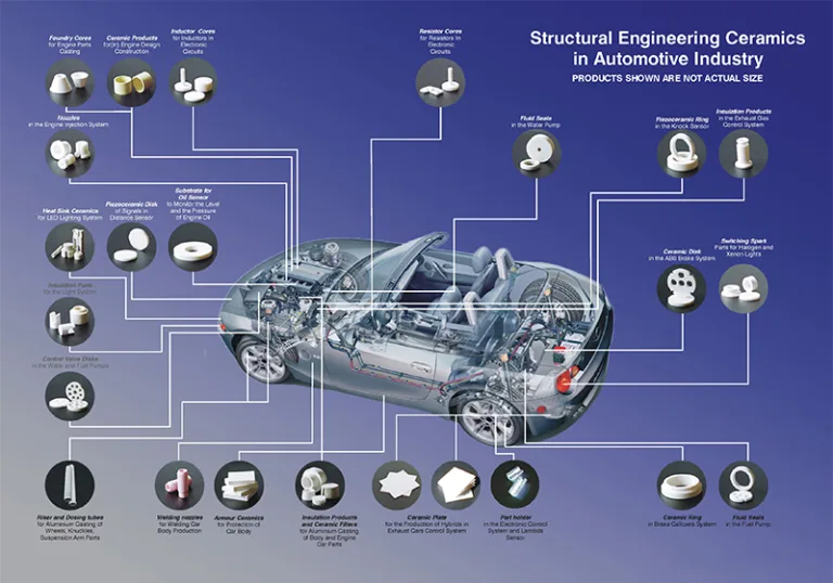
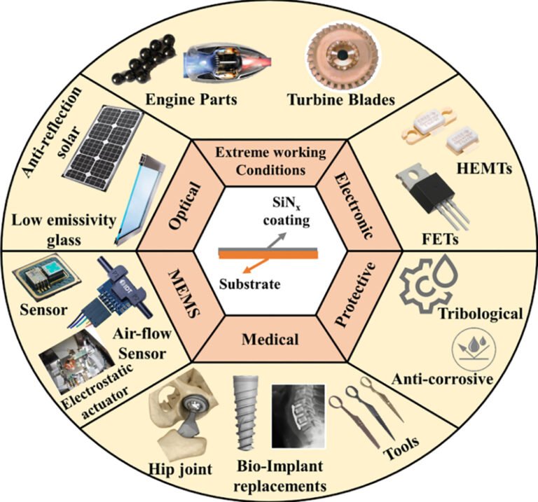
Against this background, advanced ceramics offer a useful set of engineering options rather than one universal solution. For example, alumina can provide electrical insulation and a stable surface, silicon nitride (Si₃N₄) combines mechanical strength with comparatively high fracture toughness for a technical ceramic, and silicon carbide (SiC) provides high hardness, wear resistance, and useful thermal conductivity in suitable grades. Consequently, engineers select each ceramic according to the function it must perform, the surrounding materials, and the actual duty cycle.
More importantly, the phrase “advanced ceramics” covers different material families and architectures. A ceramic-coated battery separator is a thin polymer membrane with an inorganic surface layer; by contrast, a silicon nitride bearing ball is a dense structural ceramic, while an active-metal-brazed (AMB) substrate combines an insulating ceramic plate with bonded copper. Therefore, buyers should not treat these three products as interchangeable simply because each contains ceramic material.
How the three application areas connect
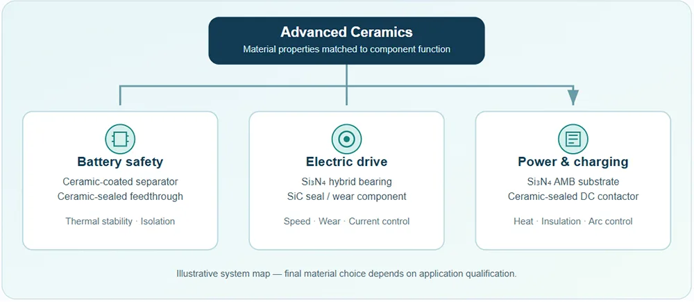
Figure 1. Six representative ceramic-enabled components across three EV application areas.
1. Battery Safety and Electrical Isolation
First, the battery system must keep its electrodes separated, manage heat, and maintain electrical insulation under vibration, temperature changes, humidity, and mechanical loading. Ceramic materials can help at two different levels: a thin ceramic coating can stabilize a separator surface, while a dense ceramic insulator can form part of a connector or feedthrough assembly. Nevertheless, neither component alone guarantees a battery pack’s safety rating; cell design, mechanical protection, sealing details, control electronics, and pack-level validation remain essential.
Representative Product 1: Ceramic-Coated Battery Separator
A ceramic-coated separator typically starts with a microporous polymer film, commonly polyethylene (PE), polypropylene (PP), or a related multilayer structure. Then, manufacturers apply a thin layer containing inorganic particles such as alumina (Al₂O₃) or boehmite, usually with a binder and a coating process selected to control adhesion, pore structure, and thickness. As a result, the coating can improve dimensional stability at elevated temperature, contribute to puncture resistance, and help the separator retain its physical barrier function when the polymer substrate begins to soften.
During cell operation, the separator allows lithium ions to pass through electrolyte-filled pores while preventing direct electronic contact between anode and cathode. When a fault produces excessive heat, however, an unreinforced polyolefin film can shrink or lose structural integrity; accordingly, a well-designed ceramic coating may reduce shrinkage and help maintain separation for a longer interval under the tested conditions. For example, a peer-reviewed study of an alumina-coated PE separator reported no measured shrinkage at 150°C for its thin-film EB-PVD sample and about 10% shrinkage at 200°C, while the tested commercial slurry-coated sample showed different results. These values describe that particular experiment rather than every commercial separator, so engineers must compare test methods, exposure time, coating design, and the full cell system before using a numeric claim in product marketing. Read the separator study.
In product development, engineers should evaluate several linked indicators instead of focusing on temperature resistance alone. These indicators include coating adhesion, thermal shrinkage, electrolyte wettability, ionic resistance, puncture strength, pore-size distribution, contamination control, and coating uniformity across the web. Moreover, a thicker or poorly bonded layer can add cost, affect cell impedance, or shed particles if the process lacks adequate controls. Therefore, the best separator balances safety margin with high-rate performance, manufacturing yield, and compatibility with the selected electrolyte and electrode chemistry.
From a procurement perspective, buyers should ask suppliers for test conditions rather than rely on broad statements such as “withstands 500°C” or “prevents thermal runaway.” A ceramic coating may improve separator thermal stability, but it does not make the polymer membrane fully ceramic or guarantee that a battery will not enter thermal runaway. Instead, the engineering value comes from a measurable change in shrinkage, integrity, and cell-level abuse behavior under defined conditions.
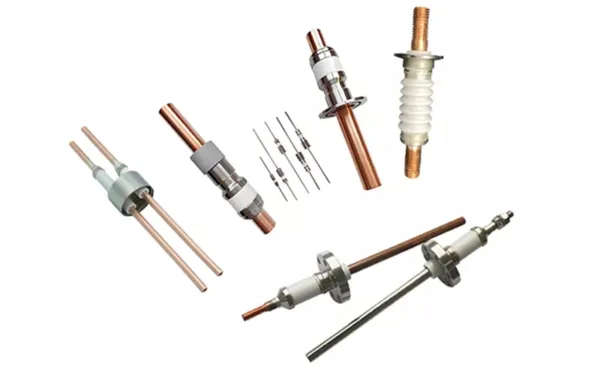
Representative Product 2: Ceramic-Sealed Connector and Electrical Feedthrough
At battery pack boundaries and other demanding electrical interfaces, a ceramic-sealed connector or feedthrough can combine a metal conductor with an electrically insulating ceramic body or seal. Typically, alumina serves as the insulating ceramic because it provides high electrical resistivity, dimensional stability, and compatibility with suitable metal joining systems. In a ceramic-to-metal assembly, designers select the metallization, brazing alloy, housing geometry, and seal design to match operating voltage, current, temperature, pressure, vibration, and the surrounding environment.
Unlike a general polymer connector, a hermetic ceramic feedthrough can support an application that needs a controlled leak rate or long-term insulation under harsh conditions. For example, designers may use ceramic-insulated terminals in sealed electrical equipment, sensors, power modules, or selected battery-related assemblies where the product architecture calls for a ceramic-to-metal barrier. Even so, not every EV battery connector uses a ceramic seal, and a ceramic component alone does not confer an IP rating such as IP67 or IP68. The complete connector or pack must meet the relevant ingress-protection, dielectric, vibration, thermal cycling, salt-spray, and pressure requirements.
Consequently, component teams should define the current path, insulation distance, creepage distance, contact resistance, sealing interface, and assembly loads before freezing a design. Additionally, thermal expansion mismatch between metal and ceramic can create stress at the joint; engineers address this mismatch through material pairing, joint geometry, compliance features, controlled brazing, and validation cycling. By treating the ceramic seal as part of an engineered interface rather than an isolated insert, developers can improve electrical isolation and environmental robustness without making unsupported assumptions about pack-level performance.
2. Electric Drive Efficiency and Durability
Next, the electric drive unit places demanding loads on rolling bearings, shafts, reduction gears, pumps, and sealing systems. High rotational speed, inverter-generated electrical effects, rapid acceleration, vibration, and compact packaging can expose weaknesses in conventional component materials. In this environment, silicon nitride balls and silicon carbide wear components solve different problems: Si₃N₄ can reduce rolling-element mass and interrupt electrical current paths in suitable hybrid bearings, whereas SiC suits wear- and corrosion-resistant sliding interfaces.
Representative Product 3: Silicon Nitride Ceramic Bearing
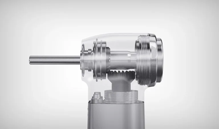
A silicon nitride hybrid bearing usually pairs steel inner and outer rings with Si₃N₄ rolling elements. Compared with steel balls, silicon nitride balls offer lower density, high hardness, strong elastic properties, corrosion resistance, and electrical resistivity. CoorsTek, for example, states that its Cerbec® silicon nitride balls are 58% lighter than steel alloys and highlights their use in EV motor shaft bearings. This product-specific figure illustrates the weight advantage; actual bearing performance still depends on the ball grade, dimensions, cage, raceway geometry, lubricant, preload, fits, and operating temperature. See CoorsTek’s EV bearing information.
Because an inverter switches current at high frequency, stray electrical current can pass through a motor bearing in some system designs. Subsequently, current discharge across the rolling contact may create microscopic craters, surface fluting, noise, vibration, and premature bearing damage. A ceramic rolling element is electrically resistive, so a hybrid bearing can interrupt one path for bearing current and reduce the risk of electrical erosion when the system integrates it correctly. However, it does not replace proper grounding, shaft-current assessment, inverter and cable design, lubrication control, or system-level validation.
Mechanically, the lower mass of a silicon nitride ball can reduce centrifugal forces at high speed, while its surface finish and contact geometry influence friction and rolling behavior. In turn, less frictional loss may support efficiency and temperature control, although grease selection, seal drag, bearing preload, and raceway finish can outweigh the material advantage in some applications. Likewise, the ceramic’s high hardness can improve wear behavior, yet its brittle fracture mode means that impact load, edge defects, contact stress, and installation procedures require careful management.
For motor designers, a hybrid bearing can be attractive where electrical erosion, speed, or grease life limits a conventional all-steel solution. Meanwhile, full ceramic bearings can suit special environments that require more extensive electrical isolation or corrosion resistance, but they often impose higher component cost and different load limits. Consequently, engineers should choose a bearing architecture from measured speed, load, duty cycle, shaft-current risk, lubrication and serviceability requirements rather than selecting ceramics simply because the vehicle uses an electric motor.
Representative Product 4: Silicon Carbide Ceramic Components
Silicon carbide (SiC) structural ceramics serve in mechanical seal faces, pump sleeves, bushings, thrust rings, and other wear parts that handle heat, abrasive particles, or chemically aggressive fluids. In an EV, a SiC component may be relevant to selected coolant pumps, thermal-management circuits, sealing assemblies, and auxiliary fluid systems, depending on the actual duty conditions and system architecture. By contrast, a SiC power semiconductor is a different product category: it uses semiconductor-grade silicon carbide to switch electrical power, whereas the structural SiC component discussed here is a dense engineering ceramic.
For sealing service, SiC provides high hardness, good corrosion resistance in many environments, useful thermal conductivity, low thermal expansion, and strong resistance to abrasion. These properties can help a mechanical seal keep its flat contact surface under pressure, speed, and temperature fluctuations. Manufacturer references describe SiC seal faces for pumps and rotating equipment, including applications that demand wear resistance and dimensional stability. Review silicon carbide seal applications.
Nevertheless, silicon carbide does not offer universal chemical immunity. Material grade, binder or free-silicon content, process chemistry, pH, temperature, concentration, and exposure time all affect compatibility; therefore, engineers must check the fluid against a grade-specific corrosion chart or test the actual assembly. In particular, procurement teams should not describe any ceramic as “resistant to every acid” without qualification. Instead, the design brief should list the coolant or fluid chemistry, possible contaminants, temperatures, pressures, flow rate, startup conditions, and acceptable leakage.
When a SiC seal replaces a metal or polymer wear surface, the system can gain longer wear life and more stable geometry, but ceramics remain brittle and may chip under installation damage or misalignment. Accordingly, teams should specify counterface material, flatness, surface finish, spring loading, lubrication regime, thermal shock, and debris management together. If a vehicle program needs a custom seal or sleeve, these details give a supplier a much stronger basis for material selection and quotation than a drawing alone.

| Product | Main engineering role | Key benefit | Important design check |
|---|---|---|---|
| Ceramic-coated separator | Electrode isolation | Improved thermal dimensional stability | Adhesion, pores, impedance and cell abuse tests |
| Ceramic-sealed feedthrough | Electrical insulation and sealing | Stable dielectric barrier in demanding interfaces | Joint stress, leak rate and dielectric withstand |
| Si₃N₄ bearing ball | High-speed rolling contact | Low mass and electrical resistance | Bearing current, lubrication and contact stress |
| SiC seal or sleeve | Fluid handling and wear control | Hardness, thermal stability and chemical resistance | Fluid compatibility, finish and impact protection |
3. Power Electronics, 800 V Systems, and Fast Charging
Finally, higher-voltage architectures and compact power modules place greater demands on thermal management, electrical insulation, and safe DC switching. Although moving toward an 800 V vehicle architecture can reduce current for a given power level, it does not eliminate heat generation or insulation challenges. Instead, inverter efficiency, switching frequency, module layout, cooling strategy, insulation distances, and package reliability jointly determine how much performance an EV system can sustain.
Representative Product 5: Silicon Nitride Ceramic Substrate for Power Modules
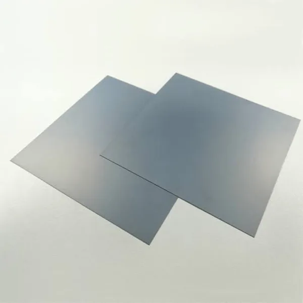
A silicon nitride AMB substrate places a ceramic plate between copper circuits and a heat-spreading or mounting structure. During active metal brazing, a controlled interfacial reaction bonds copper to the ceramic, creating a substrate that combines copper’s electrical and thermal conductivity with the ceramic’s insulation and mechanical support. Manufacturers use these substrates in power modules built around IGBTs and silicon carbide MOSFETs, including traction inverters and other high-power conversion equipment.
Silicon nitride attracts module designers because it can combine useful thermal conductivity with high bending strength and fracture toughness. For example, Heraeus Electronics lists a representative Si₃N₄ AMB substrate with thermal conductivity of at least 80 W/(m·K), bending strength of at least 650 MPa, fracture toughness of at least 6 MPa·m1/2, and a typical thermal expansion coefficient near 2.6 ppm/K for its stated material and test conditions. Those figures describe a specific product grade rather than every silicon nitride substrate on the market. See the manufacturer’s substrate data.
In an inverter, power semiconductor chips create heat while switching large currents. The substrate must conduct that heat toward the cooler, electrically isolate live copper features from the baseplate, and tolerate repeated changes in temperature. Consequently, thermal conductivity is only one selection metric; bending strength, fracture toughness, ceramic thickness, copper thickness, bond quality, metallization pattern, flatness, and thermal cycling performance matter as well. A substrate with a very high conductivity value may not be optimal if it cannot meet the module’s mechanical and reliability requirements.
Moreover, the coefficient of thermal expansion influences mismatch between silicon chips, copper, ceramic, solder or sinter layers, and the baseplate. Each interface expands differently during power cycling, so repeated thermal strain can promote fatigue, delamination, or cracking. Silicon nitride’s mechanical robustness can provide a useful design margin for demanding modules, but the team still needs to validate the complete stack through power cycling, thermal cycling, insulation testing, partial-discharge evaluation where applicable, and assembly-process controls.
For buyers, useful questions include: Does the module call for AMB or another metallization technology? What thicknesses of ceramic and copper fit the current and heat-flux requirements? Which surface finish, pattern, bow, and positional tolerances does assembly require? Finally, which reliability tests and acceptance limits will qualify the substrate for the vehicle’s lifetime? Clear answers help buyers compare total system value rather than thermal conductivity alone.
Representative Product 6: Ceramic-Sealed High-Voltage DC Relay or Contactor
High-voltage battery packs and charging systems need a controlled way to connect and disconnect DC power. A high-voltage DC relay, commonly called a contactor in traction applications, uses contacts and an arc-management design to interrupt current safely under its rated conditions. In some product architectures, a ceramic-sealed chamber encloses the contacts and a controlled gas atmosphere, while magnetic blowout or other design features help move and extinguish the DC arc.
Unlike low-voltage switching, DC interruption at high voltage can sustain an arc because the current lacks the natural zero crossings that help an AC arc extinguish. Therefore, the relay needs coordinated contact geometry, contact material, gas management, insulation, sealing, magnetic blowout or another arc-control mechanism. Ceramic sealing supports containment and electrical isolation in certain high-voltage relay designs; however, the ceramic component is part of a broader system and does not alone prevent fire or guarantee a safe disconnect.
Commercial product information illustrates this approach. For example, Hongfa describes high-voltage DC relays with a ceramic-brazed sealing structure and magnetic arc-extinguishing design for new-energy vehicles, charging piles, energy storage, and related power systems. TE Connectivity also lists hermetically sealed high-voltage contactors using ceramic sealing technology for applications that include EV chargers and battery energy storage. View Hongfa’s high-voltage DC relay overview and TE Connectivity’s sealed contactor range.
During supplier evaluation, engineers should align continuous current, make and break capacity, rated voltage, short-circuit coordination, coil power, contact resistance, insulation resistance, dielectric withstand, operating temperature, vibration, altitude, and service life with the electrical architecture. Furthermore, validation should consider both normal operation and fault scenarios, including contact welding, failed opening, repeated switching, pre-charge sequencing, and exposure to moisture or contamination. For fast-charging infrastructure, the contactor must also match the charger’s system voltage and current, because the relay rating alone does not determine the charging power delivered to a vehicle.
A practical system view: ceramic parts work as a team
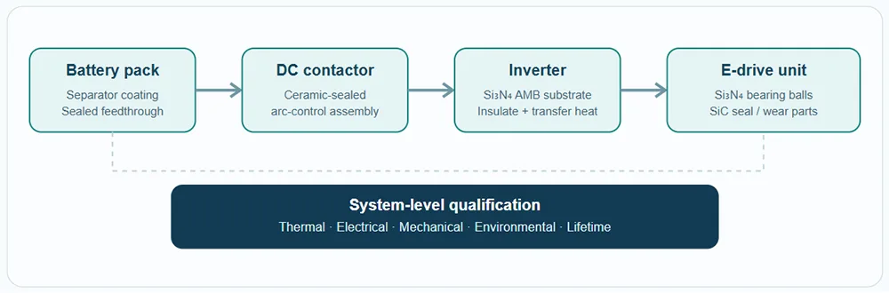
Figure 2. Simplified functional map; actual vehicle architectures and component locations vary by design.
How to Select Advanced Ceramic Components for an EV Program
Before specifying a ceramic component, start with the failure mode that the design needs to address. For example, battery engineers may want to reduce separator shrinkage, maintain electrical isolation, or improve a sealed electrical interface; meanwhile, e-drive engineers may need to mitigate bearing-current damage, reduce rolling-element mass, or extend a seal’s wear life. In power modules, the key challenge may be to balance heat transfer, electrical insulation, thermal expansion, and mechanical fatigue.
Next, create a measurable operating envelope. Include nominal and peak temperature, temperature ramp rate, voltage, current, speed, load, vibration, fluid chemistry, contamination, duty cycle, expected lifetime, and any fault conditions. Then, identify the specific material grade and manufacturing route rather than using a broad material name alone. For example, different SiC grades can have different microstructures and chemical behavior, while silicon nitride substrate grades can vary in conductivity, toughness, strength, and thermal expansion.
After that, assess the whole component and its interfaces. Dense ceramics may need grinding and polishing to achieve critical dimensions or surface finish; ceramic-metal assemblies require control of joining stress and leak integrity; separator coatings require consistent web coating, pore structure, and adhesion; and AMB substrates require controlled copper bonding, flatness, pattern accuracy, and thermal-cycle reliability. Because ceramics often fail from local defects or stress concentrations, material cleanliness, edge design, inspection method, handling, and assembly force deserve the same attention as the nominal property data.
Furthermore, request evidence appropriate to the risk level. Useful documentation may include material certificates, traceability, dimensional inspection, surface and microstructure checks, dielectric testing, leak testing, thermal cycling, power cycling, fatigue or wear results, and failure-analysis capability. Where an automotive customer requires a specific quality management system, PPAP package, IATF 16949 certification, or other compliance evidence, buyers should verify the supplier’s actual status and define deliverables contractually rather than assuming that every ceramic supplier meets those requirements.
Finally, compare total system cost instead of unit price in isolation. A ceramic part may cost more than a metal or polymer alternative, yet it can justify that premium if it reduces failure rates, enables compact packaging, lowers maintenance, or improves energy conversion efficiency over the vehicle’s lifetime. Conversely, ceramic is not automatically the right answer when impact toughness, easy joining, high production volume, or low initial cost dominates the specification. A sound material decision weighs benefits, limits, manufacturing yield, qualification time, and the cost of failure together.
Where Custom Component Engineering Adds Value
For OEMs and Tier suppliers, an early design-for-manufacturing review can reveal avoidable risks before tooling or validation begins. A useful review checks geometry, tolerance stack-up, material availability, finishing allowance, joining interfaces, inspection access, and batch-to-batch consistency. In projects involving small complex metal or ceramic-injection-molded features, AOFE MIMCustom can be included in the supplier discussion for MIM/CIM design and tooling feasibility; however, teams should confirm the exact material scope, production capability, automotive quality documentation, and qualification responsibilities for each individual project.
For battery, drive and power-electronics applications, a well-prepared RFQ should include the 2D drawing and 3D CAD model, material grade or performance target, operating environment, annual volume, critical-to-quality dimensions, surface finish, joining requirements, inspection plan, and relevant validation standards. With those inputs, the supplier can assess manufacturability and identify where prototype testing or material screening is necessary before moving toward series production.
Frequently Asked Questions
Why do EV battery separators use ceramic coatings?
Ceramic coatings can help reduce thermal shrinkage, strengthen the separator surface, and support electrode separation under elevated-temperature conditions. However, cell safety still depends on the complete separator design, electrolyte, electrodes, thermal management, protection systems, and validated abuse performance.
What is the role of silicon nitride bearings in EV motors?
In suitable hybrid bearings, Si₃N₄ balls reduce rolling-element mass and provide electrical resistance that can interrupt some bearing-current paths. Bearing selection still requires speed, load, lubrication, fits, and system-level shaft-current analysis.
Why do power modules use silicon nitride ceramic substrates?
Si₃N₄ AMB substrates combine an insulating ceramic with bonded copper conductors, supporting heat transfer, electrical isolation, mechanical strength, and thermal-cycle robustness in demanding power modules. The suitable grade depends on the stack design and qualification targets.
Are silicon carbide ceramic parts the same as SiC power semiconductors?
No. Structural SiC ceramics serve in seal faces, sleeves, bushings, and wear parts, whereas SiC power semiconductors use controlled semiconductor material and device structures to switch electrical energy. Their compositions, processing routes, and qualification requirements differ.
Does a ceramic-sealed DC contactor make a vehicle or charger completely safe?
No single component can guarantee overall safety. Ceramic sealing can support containment and insulation in certain contactor designs, while safe switching also depends on contact materials, arc-control design, ratings, protection coordination, mounting, sensing, and system validation.
What should a buyer provide when requesting a custom ceramic component?
A buyer should share drawings or CAD files, material requirements, operating temperature and environment, mechanical and electrical loads, fluid chemistry if relevant, annual volume, critical dimensions, surface finish, validation requirements, and expected service life. Clear inputs help suppliers judge feasibility and quote consistently.
Turn Ceramic Material Potential into Component Performance
Advanced ceramics create the most value when engineers match material properties to a defined failure mode and validate the complete assembly under realistic conditions. Whether the priority is battery insulation, e-drive durability, inverter thermal management, or high-voltage switching, early collaboration between design, material, manufacturing, and quality teams helps reduce avoidable qualification risk.
For supplier discussions, prepare the part drawing, performance targets, annual demand, and required validation evidence before asking for a quotation. That process turns a generic “ceramic part” request into a technically actionable project brief.
Technical References and Further Reading
- ACS Omega, “Binder-Free, Thin-Film Ceramic-Coated Separators for Improved Safety of Lithium-Ion Batteries” (2021). Full text.
- CoorsTek, “Cerbec® Bearing Balls for EV Traction Motors.” Product and application information.
- CoorsTek, “Silicon Carbide Mechanical Seals.” Material and seal applications.
- Heraeus Electronics, “Silicon Nitride AMB Substrates.” Product data and material specifications.
- NGK, “AMB Substrates for Power Modules.” Substrate structure and applications.
- Hongfa, “High Voltage DC Relay.” Ceramic-brazed seal and arc-control overview.
- TE Connectivity, “High Voltage Contactors, Hermetically Sealed, Ceramic Technology.” Product overview.
Engineering note: Material and product figures in this article refer to cited grades or tests where indicated. Actual results vary by component geometry, process, operating conditions, test protocol, and system integration; suppliers should confirm current specifications before design release.