Custom Metal Manufacturing · OEM Support
Metal Injection Molding Services for Complex Precision Metal Parts
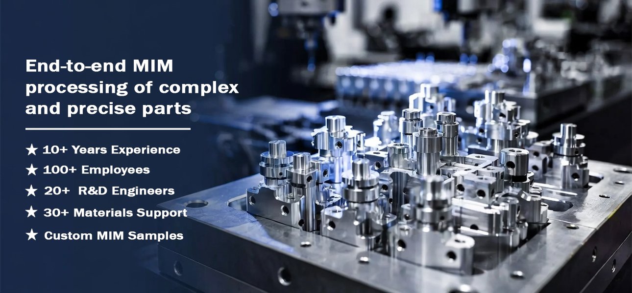
For OEM projects that require small, complex metal components, metal injection molding (MIM) can combine intricate geometry with repeatable, high-volume production. By integrating material selection, tooling, molding, debinding, sintering, and finishing into a coordinated process, AOFE MIMCustom helps customers evaluate suitable manufacturing routes for custom metal parts.
Before production begins, however, each design needs a practical review of geometry, material, expected volume, shrinkage, tolerance, surface finish, and final application requirements.
MIM Fundamentals
What Is Metal Injection Molding and When Should You Consider It?
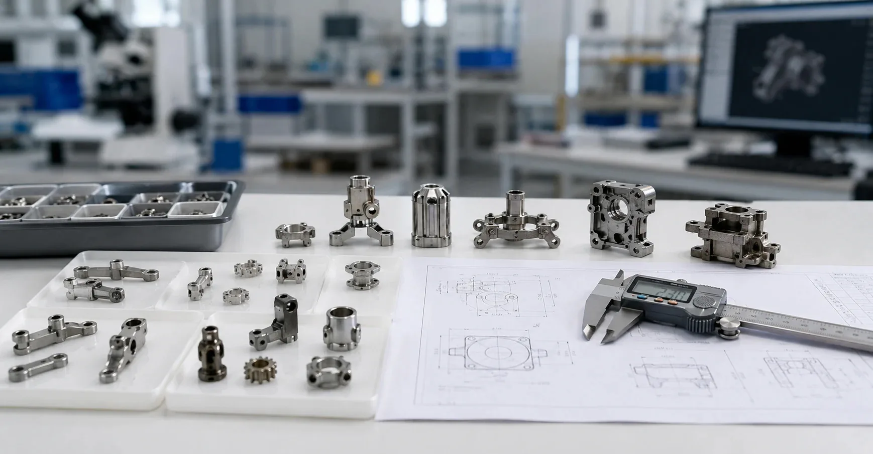
In simple terms, metal injection molding combines fine metal powder with a binder to create a feedstock that can fill a mold. After molding, the component moves through debinding and sintering; consequently, the metal particles bond into a dense part, subject to the selected material system and process conditions.
For projects with complex three-dimensional features and repeat production demand, MIM may reduce the need for extensive machining or the assembly of multiple separate pieces. Nevertheless, engineers should compare the complete manufacturing route rather than assuming that MIM always offers the lowest cost.
01 · Process Logic
First, metal powder and binder form a moldable feedstock; next, molding, debinding, and sintering create the component, followed by any specified finishing operations.
02 · Suitable Geometry
Typically, MIM deserves evaluation when small components include ribs, holes, slots, curved surfaces, or multiple integrated features that complicate conventional machining.
03 · Early Review
Before tooling, engineers should examine shrinkage, dimensional requirements, material behavior, finishing needs, and the expected production volume.
Suitability Screening
Is Metal Injection Molding Suitable for Your Part?
Before committing to a mold, evaluate the component’s geometry, annual demand, target alloy, critical dimensions, and surface requirements. In particular, MIM becomes more attractive when the design benefits from integrated features and the production volume can support tooling and process development.
Usually Worth Evaluating
- Small metal parts with complex three-dimensional geometry.
- Components with holes, slots, ribs, bosses, or integrated features.
- Repeat-production programs with a realistic volume forecast.
- Designs where near-net-shape manufacturing may reduce machining or assembly.
- Projects with defined alloy, tolerance, finishing, and inspection requirements.
- OEM components that can justify tooling and process qualification.
May Need Another Process
- Large, heavy, or geometrically simple components.
- One-off prototypes or very low quantities that cannot justify tooling.
- Designs that continue to change before requirements stabilize.
- Parts with challenging distortion risks or oversized thick sections.
- Components that require extremely tight tolerances across every feature without secondary correction.
- Parts that stamping, CNC machining, casting, or another route can produce more economically.
Engineering note: Because debinding and sintering affect the final shape, a part that fills the mold successfully may still present dimensional challenges later. Therefore, review the drawing and functional requirements before approving tooling.
Not Sure Whether Your Part Fits MIM?
To start a useful feasibility review, prepare the drawing, target material, estimated annual volume, and critical dimensions.
Engineering Review Before Tooling
What AOFE MIMCustom Reviews Before Production
For a custom MIM project, AOFE MIMCustom can use the customer’s drawings and requirements as the starting point for discussing manufacturability, material selection, process needs, and finishing expectations. Ultimately, the scope and feasibility of each project depend on the actual component and confirmed production requirements.
Part Geometry
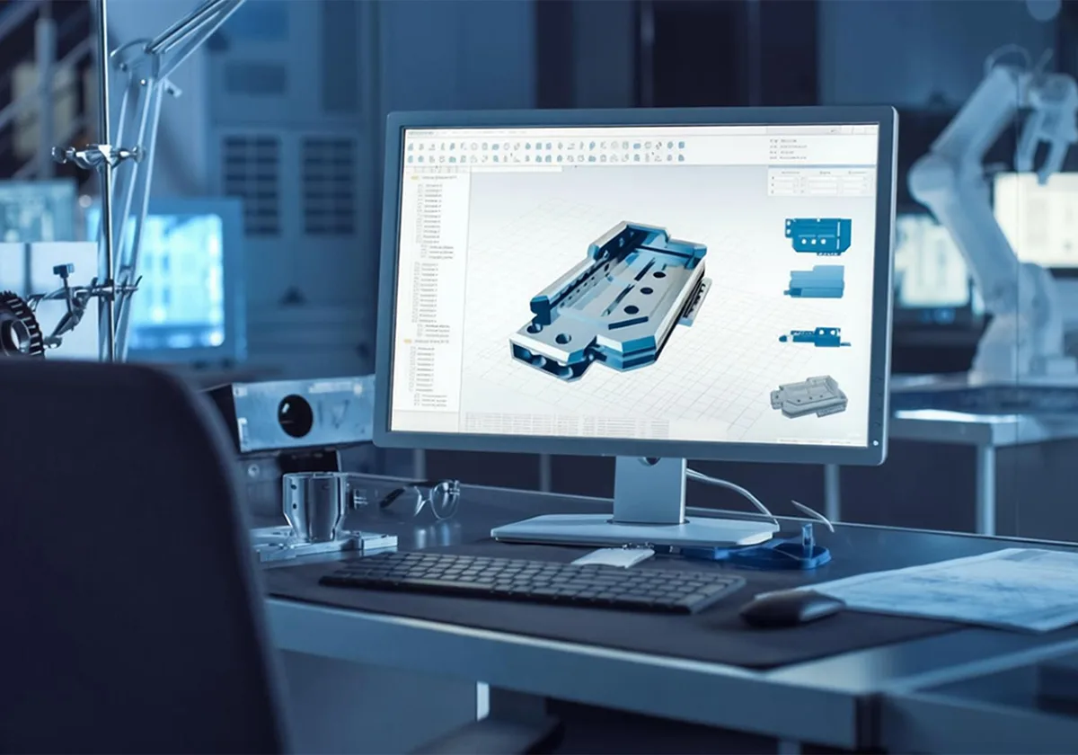
First, review wall transitions, ribs, holes, undercuts, gate implications, and areas that may deform during processing.
Material Target
Next, consider corrosion resistance, strength, hardness, magnetic response, heat treatment, and the operating environment.
Volume and Tooling
Meanwhile, compare estimated annual demand, tooling investment, secondary operations, and the expected cost per acceptable part.
Tolerance and Finishing
Finally, identify critical dimensions, datum surfaces, surface finish, machining allowance, coatings, and inspection criteria.
Not every complex part should move directly into tooling. Instead, a drawing-based discussion helps establish whether the proposed material and process route can meet the required functional and commercial objectives.
MIM Process Chain
How the Metal Injection Molding Process Works
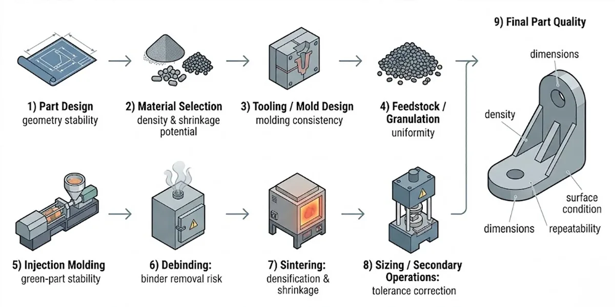
A successful MIM component depends on how each manufacturing stage supports the next one. For example, feedstock consistency affects molding, while debinding and sintering influence the final density, dimensions, and structural performance.
STEP 01
Feedstock Preparation
First, fine metal powder combines with a suitable binder system to create a feedstock with the flow and handling properties required for molding.
STEP 02
Injection Molding
Next, molding equipment injects the feedstock into a tool to form the green part, while process settings influence feature definition and consistency.
STEP 03
Debinding
After molding, a controlled debinding route removes the binder; careful support and process control help reduce cracking and deformation risks.
STEP 04
Sintering
Subsequently, the selected sintering cycle bonds the metal particles and causes shrinkage, which must be considered in the dimensional strategy.
STEP 05
Secondary Operations
Where specifications require additional control, machining, sizing, heat treatment, polishing, plating, or PVD may follow sintering.
STEP 06
Inspection and Release
Finally, the inspection plan checks the agreed dimensions, material requirements, appearance, and functional criteria before acceptance.
Process note: a component may fill the mold successfully yet fail final acceptance if shrinkage, sintering distortion, finishing, or inspection requirements receive insufficient attention. Therefore, review the complete process chain before production release.
Process Selection
When Should You Compare MIM with CNC, Powder Metallurgy, Casting, or Metal 3D Printing?
Several manufacturing routes can produce metal components, but each one has different design limits and cost drivers. Accordingly, the best choice depends on part geometry, material, expected volume, tooling requirements, tolerances, and finishing needs.
| Manufacturing Route | Potential Advantage | Key Consideration |
|---|---|---|
| Metal Injection Molding | Complex small parts and repeat production. | Tooling investment, shrinkage control, and sintering requirements. |
| CNC Machining | Flexible design changes and precise feature machining. | Material removal, machining time, and access to complex features. |
| Conventional Powder Metallurgy | Suitable pressed shapes and established production routes. | Geometry restrictions associated with pressing and tooling. |
| Casting | A broad range of component sizes and geometries, depending on the casting process. | Alloy compatibility, wall thickness, detail, and finishing requirements. |
| Metal 3D Printing | Design iteration and complex geometries without conventional production tooling. | Build rate, material route, post-processing, and production economics. |
Process selection note: MIM does not automatically outperform other methods. Instead, compare the total cost of tooling, manufacturing, finishing, inspection, and rejected parts at the expected production volume.
Material Selection
MIM Materials for Custom Metal Components
Material choice influences strength, corrosion resistance, hardness, magnetic properties, heat treatment, finishing, and the final application. Therefore, AOFE MIMCustom should evaluate the requested alloy alongside the component’s geometry, performance targets, production route, and inspection criteria.
Stainless Steels
For example, 316L, 304, 17-4PH, 420, and 440C may be considered for different combinations of corrosion resistance, strength, hardness, and wear performance.
Final properties depend on the alloy, processing conditions, heat treatment, and applicable specification.
Tool and Low-Alloy Steels
When a component needs strength, hardness, or wear resistance, suitable tool steels and low-alloy systems may warrant review.
Meanwhile, heat treatment and finishing requirements should be established before production.
Titanium Alloys
For applications that prioritize a high strength-to-weight ratio or specific corrosion performance, titanium alloy options may be considered where a suitable MIM material route is available.
However, alloy availability and process feasibility require project-specific confirmation.
Copper and Specialty Alloys
Copper-based, soft magnetic, tungsten-based, or other specialty materials may suit projects with specific electrical, magnetic, density, or functional requirements.
In each case, confirm the exact grade and processing capability before design approval.
Material note: an alloy that performs well in machining or casting may require a different process assessment for MIM. Consequently, verify feedstock availability, sintering behavior, final properties, and acceptance requirements before confirming the material.
Design, Shrinkage, and Tolerance
Design Considerations Before MIM Tooling
Because the molded green part changes during debinding and sintering, the final dimensions do not simply match the mold cavity. Accordingly, the design review should consider shrinkage compensation, wall balance, support, datum strategy, and the features that may need secondary machining.
Shrinkage and Geometry
First, evaluate wall thickness transitions, long thin features, unsupported sections, and areas that may experience differential shrinkage or distortion.
Tolerance Strategy
Next, identify functional dimensions and assembly interfaces rather than assigning the tightest tolerance to every feature without a technical reason.
Secondary Operations
Where necessary, plan machining, sizing, grinding, polishing, heat treatment, plating, or PVD around the finished component’s requirements.
Why As-Sintered Dimensions May Not Be Enough
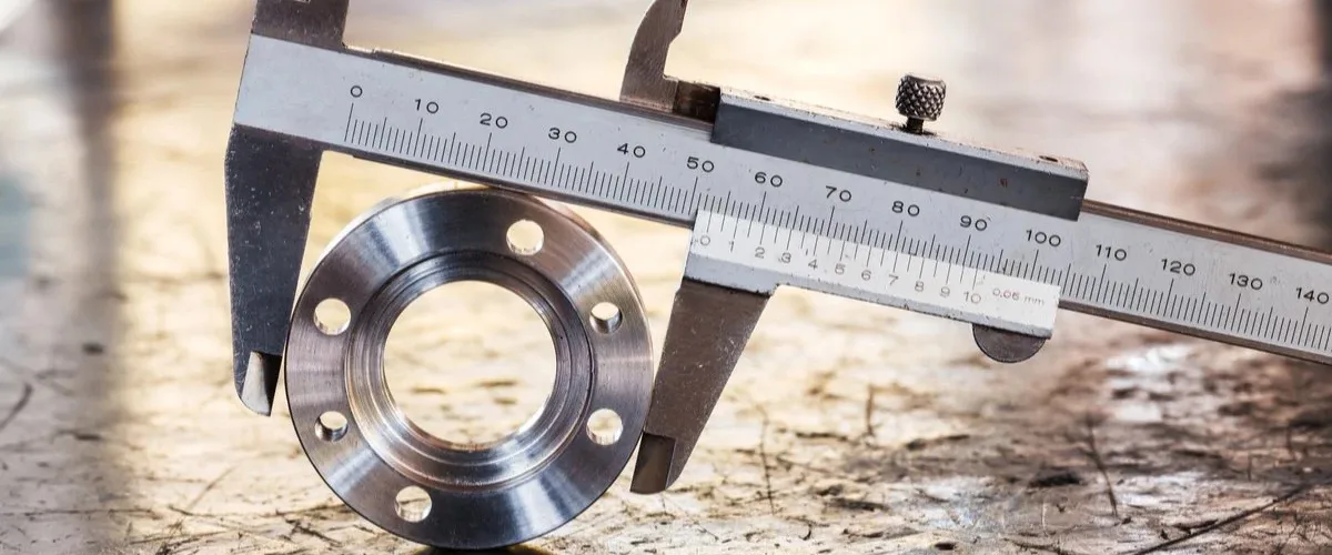
For some applications, the as-sintered condition can meet the design requirements. However, threads, precision bores, sealing faces, and critical assembly interfaces may require additional finishing or dimensional correction.
Plan Inspection Around Functional Risk
In addition, the inspection plan should cover the dimensions and properties that determine whether the component works as intended. Depending on the specification, this may include dimensional measurement, visual checks, material verification, density or porosity assessment, surface condition, and coating requirements.
Important: A single tolerance or surface-finish value cannot apply to every MIM design. Instead, confirm achievable limits against the drawing, material, geometry, process route, and any secondary operations.
Application Areas
Industries and Applications for Custom MIM Parts
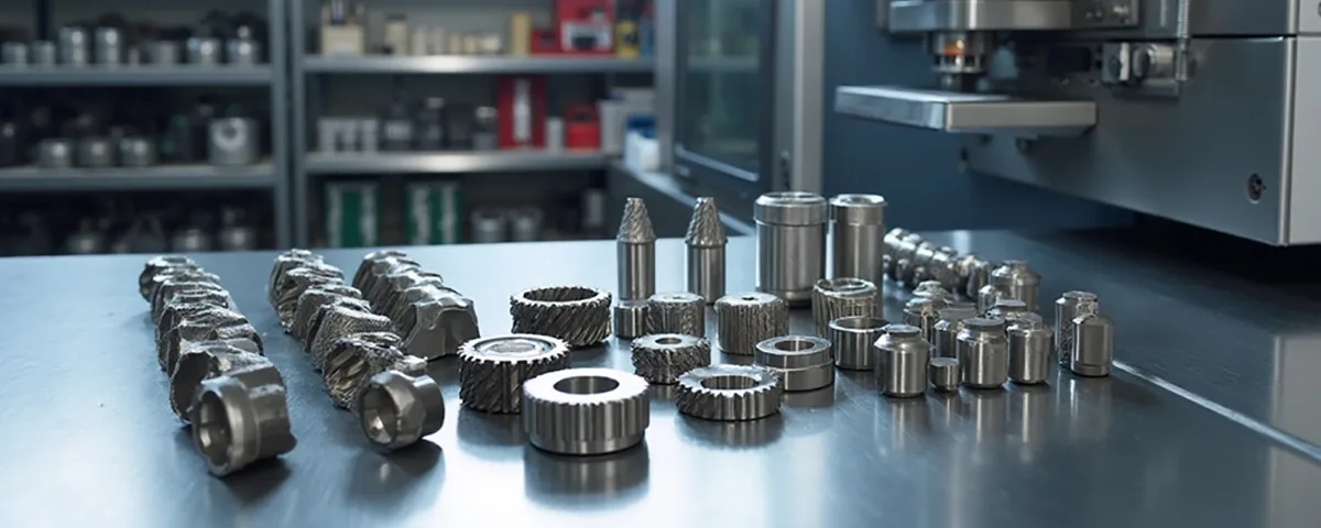
Across several industries, MIM can support small metal components that combine complex geometry with repeat manufacturing needs. Nevertheless, the material, part design, regulatory requirements, and production route must match the intended application.
Consumer Electronics
For compact devices, MIM may suit small hinges, brackets, buttons, connector components, and structural metal features when material and design requirements align.
Medical Devices
For medical and dental equipment, selected MIM components may support compact mechanisms and intricate metal shapes, subject to applicable material, cleanliness, validation, and regulatory requirements.
Automotive
Within automotive systems, MIM may be considered for locking mechanisms, sensors, connectors, compact functional parts, and other components that require repeatable production.
Industrial Tools
For industrial tools, suitable MIM applications may include compact wear components, tool mechanisms, and metal hardware with demanding geometric details.
Robotics and Automation
For robotics systems, MIM may be relevant to compact gears, gripper components, brackets, and motion-related parts when the alloy and design support the required function.
Drones and Portable Equipment
For drones and portable equipment, small brackets, locking features, motor-related components, and compact structural parts may warrant review when strength, mass, and repeatability matter.
AOFE MIMCustom Project Support
From Drawing Review to Custom MIM Components
As a custom manufacturing service provider, AOFE MIMCustom focuses on helping customers assess metal injection molding requirements for their components. To establish a clear production plan, each project should define the drawing revision, material grade, critical dimensions, surface finish, estimated quantity, and acceptance criteria.
A Practical Project Review
First, define the component’s function and critical features.
Next, evaluate the material, geometry, and manufacturing route against the requirements.
Then, clarify any tooling, finishing, or inspection needs before confirming the project scope.
Finally, align the quotation and production plan with the agreed specifications and quantity forecast.
For the most useful technical review, customers should provide a 2D drawing and, where available, a 3D CAD model. Additionally, include the target alloy, critical tolerances, surface requirements, application environment, and expected annual volume.
Frequently Asked Questions
Metal Injection Molding: Common Questions
1. Which parts are good candidates for metal injection molding?
Generally, MIM suits small, complex metal parts with repeat production demand and features that may be difficult or expensive to machine. However, engineers should assess geometry, material, tolerance, volume, and finishing requirements before selecting the process.
2. Which materials can MIM use?
Depending on feedstock availability and project feasibility, MIM may use stainless steels, low-alloy steels, tool steels, soft magnetic materials, and selected specialty alloys. Therefore, confirm the exact grade and required final properties during the material review.
3. Why does sintering affect final dimensions?
During sintering, the metal particles bond and the part shrinks as it densifies. Consequently, the mold design, process conditions, geometry, and inspection strategy must account for dimensional changes.
4. Can MIM replace CNC machining?
In some high-volume projects, MIM can reduce machining time by forming complex features close to their final shape. Nevertheless, CNC machining may remain preferable for low quantities, frequent design changes, or features that require extensive precision correction.
5. Can MIM parts receive secondary finishing?
Yes, depending on the alloy and component design, secondary operations may include machining, sizing, heat treatment, polishing, plating, or PVD coating. Accordingly, specify the required finish and critical dimensions before quotation.
6. What information should I provide for a quotation?
To support a meaningful quotation, provide a 2D drawing, a 3D model if available, target material, annual quantity, critical dimensions, surface finish, and application details. Additionally, identify any required inspection reports, certifications, or special packaging conditions.
7. How can AOFE MIMCustom assess my project?
Start by sharing your component drawing and production requirements with AOFE MIMCustom. After reviewing the available information, the team can discuss material suitability, manufacturing considerations, finishing needs, and the next steps required to evaluate the project.
Start Your MIM Project
Ready to Review Your Custom Metal Part?
Share your drawing, material target, critical tolerances, finishing requirements, and estimated annual volume. With these details, AOFE MIMCustom can begin discussing manufacturing feasibility and the information needed for a project quotation.
For faster review, include the latest drawing revision and identify all critical-to-function dimensions.