Advanced Ceramics | Materials Engineering | Precision Components
Which Is Better: Silicon Nitride Centering Pins or Zirconia Centering Pins?
Choosing between silicon nitride and zirconia centering pins requires more than comparing ceramic hardness. Instead, engineers must evaluate dimensional stability, thermal expansion, fracture toughness, wear behavior, operating temperature, and alignment accuracy. Although both materials support precision positioning, each offers different advantages under demanding industrial conditions.
In general, silicon nitride (Si₃N₄) suits lightweight, high-speed, and thermally demanding assemblies, whereas zirconia (ZrO₂), particularly yttria-stabilized zirconia, suits applications that prioritize fracture toughness and resistance to mechanical damage. Ultimately, the better choice depends on the actual loads, clearances, environment, and required service life.
Quick Answer: Which Ceramic Should You Choose?
Choose silicon nitride centering pins when low component mass, low thermal expansion, good thermal shock resistance, and high-speed operation are important. Moreover, its combination of stiffness and low density can help engineers reduce moving mass while maintaining accurate positioning.
Choose zirconia centering pins when high fracture toughness, dimensional precision, and resistance to certain forms of mechanical damage take priority. In particular, yttria-stabilized zirconia offers transformation toughening, which can help resist crack propagation.
Before making the final decision, compare the actual ceramic grades, pin geometry, load direction, mounting method, surface finish, and operating environment. Consequently, a technically suitable material may outperform a nominally harder or more expensive alternative in the real assembly.
1. What Are Ceramic Centering Pins?
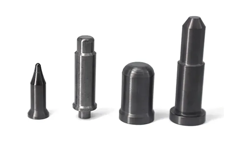
Ceramic centering pins are precision-engineered components that locate, align, or position parts within mechanical assemblies. For example, engineers use them to establish repeatable positions between machine components, guide fixtures during assembly, and maintain alignment in equipment that operates under demanding thermal or chemical conditions.
Unlike ordinary metal pins, advanced ceramic pins can offer low thermal expansion, high hardness, electrical insulation, and excellent resistance to many corrosive environments. However, ceramics remain brittle materials, so designers must consider tensile stress, bending loads, edge damage, and installation forces rather than relying on compressive strength alone.
How Does a Centering Pin Maintain Accuracy?
During assembly, a centering pin enters a corresponding hole, locating bore, or precision interface. Consequently, its diameter, cylindricity, straightness, surface roughness, and positional relationship with adjacent features influence the final alignment.
In high-precision systems, even a small dimensional change can affect repeatability. Therefore, engineers should evaluate the pin and its mating component as one tolerance system, including the effects of temperature, fit, surface contact, and mounting stress.
Key Design Parameters
- Diameter and tolerance: Determine the fit and initial positioning accuracy.
- Straightness and cylindricity: Influence repeatable alignment along the pin axis.
- Surface finish: Affects insertion, friction, contact stress, and wear.
- Thermal expansion: Determines how the fit changes as temperature rises or falls.
- Mechanical loading: Includes compression, bending, shear, vibration, and impact.
- Mounting design: Controls stress concentration, retention, and the risk of ceramic damage.
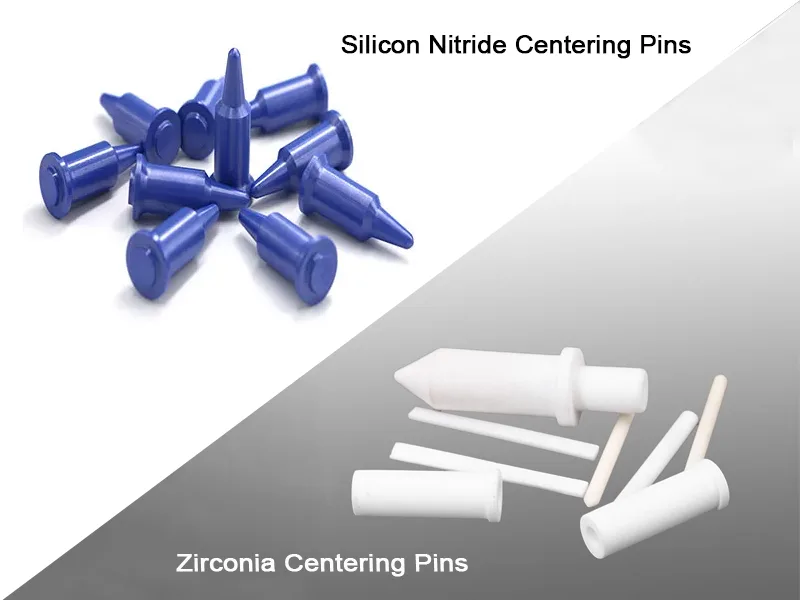
2. Silicon Nitride Centering Pins: Lightweight Precision for Demanding Environments
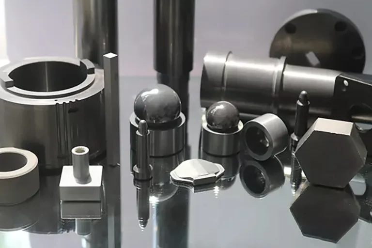
Silicon nitride centering pins use silicon nitride, Si₃N₄, an advanced structural ceramic known for its favorable combination of low density, high strength, stiffness, wear resistance, and thermal stability. In addition, the material maintains useful mechanical properties at temperatures where many conventional engineering materials lose stiffness or strength.
Unlike zirconia, silicon nitride has a relatively low coefficient of thermal expansion and generally higher thermal conductivity. As a result, properly designed Si₃N₄ pins can reduce thermal dimensional changes and respond more effectively to some temperature gradients.
2.1 Important Material Properties
- Low density: Typical dense silicon nitride has a density of approximately 3.2-3.3 g/cm³, making it substantially lighter than zirconia.
- High mechanical strength: Many engineering grades provide flexural strength in the approximate range of 600-1,000 MPa, although the actual value depends on composition, processing, test method, and component geometry.
- High stiffness: A typical Young’s modulus of approximately 280-320 GPa helps limit elastic deformation under comparable loading conditions.
- Low thermal expansion: A coefficient of approximately 2.8-3.3 × 10⁻⁶/K helps limit thermally induced dimensional changes.
- Good thermal conductivity: Many grades fall around 15-30 W/(m·K), although specialized formulations can differ considerably.
- High hardness: Depending on grade and measurement method, hardness often falls within approximately 1,400-1,800 HV.
- Electrical insulation: Silicon nitride generally provides electrical insulation, making it useful in selected electrically sensitive assemblies.
Furthermore, silicon nitride offers good resistance to thermal shock in many demanding applications because its low thermal expansion and relatively high thermal conductivity can reduce thermal stress. Nevertheless, actual thermal-shock performance depends on temperature gradients, component thickness, surface condition, and the specific grade.
2.2 Why Engineers Use Silicon Nitride for Centering Pins
In high-speed machinery, low density can reduce the inertia of moving components. Consequently, a silicon nitride pin may be advantageous when the pin moves with a mechanism or when a design benefits from reducing reciprocating or rotating mass.
Similarly, low thermal expansion helps preserve dimensional relationships as operating temperature changes. For precision equipment, this characteristic can support alignment stability, provided that the mating components and mounting structure exhibit compatible thermal behavior.
In addition, high hardness and suitable wear resistance can help maintain the pin’s working surface during repeated contact. However, wear life depends on the mating material, lubrication, abrasive particles, contact pressure, surface finish, and alignment.
Best-Fit Conditions for Silicon Nitride
Consider Si₃N₄ when the assembly combines high positioning accuracy with low moving mass, temperature variation, demanding wear conditions, or a need for electrical insulation. However, verify its suitability whenever the pin experiences severe direct impact, tensile stress, sharp-edge loading, or difficult installation conditions.
3. Zirconia Centering Pins: Toughness and Dimensional Precision
Zirconia centering pins use zirconium dioxide, ZrO₂, an advanced ceramic valued for its high fracture toughness, strength, hardness, and ability to achieve precise dimensions through controlled manufacturing and finishing. For demanding mechanical interfaces, these properties make zirconia an important alternative to silicon nitride.
In particular, engineers commonly select yttria-stabilized tetragonal zirconia polycrystal, often abbreviated Y-TZP, for precision components. This material can exploit transformation toughening, a mechanism in which stress near a developing crack can trigger a crystallographic transformation that helps resist crack propagation.
3.1 Important Material Properties
- High density: Typical dense zirconia has a density of approximately 5.7-6.1 g/cm³, depending on the formulation.
- High fracture toughness: Many Y-TZP grades provide approximately 6-10 MPa·√m, although composition, aging, microstructure, and measurement method influence the result.
- High hardness: Typical Y-TZP hardness often falls around 1,100-1,400 HV, depending on the grade and test method.
- High flexural strength: Many commercial grades offer approximately 800-1,200 MPa under specified test conditions; actual values vary with grade and processing.
- High stiffness: Young’s modulus commonly falls around 200-220 GPa for Y-TZP grades.
- Low thermal conductivity: Many zirconia grades provide approximately 2-3 W/(m·K), which is much lower than the typical value for silicon nitride.
- Higher thermal expansion: A typical coefficient is approximately 9-11 × 10⁻⁶/K, depending on composition and temperature range.
Because of its transformation-toughening mechanism, zirconia can resist crack propagation more effectively than many other structural ceramics. Therefore, it deserves serious consideration when the pin may encounter mechanical shock, accidental contact, or stress concentrations.
Nevertheless, zirconia is not immune to brittle fracture. Excessive interference fits, sharp shoulders, impact against hard edges, surface defects, or unsuitable operating environments can still damage the component.
3.2 Why Engineers Use Zirconia for Centering Pins
When a centering pin must withstand challenging mechanical contact, zirconia’s fracture toughness can provide an important design advantage. Moreover, precision-ground zirconia can support close dimensional tolerances and smooth contact surfaces.
Zirconia’s lower thermal conductivity may also be useful in assemblies where heat transfer through the pin should remain limited. However, this feature can become a disadvantage when rapid heat dissipation or strong thermal-shock resistance matters.
Best-Fit Conditions for Zirconia
Consider zirconia when fracture toughness, resistance to crack growth, and precise locating surfaces are priorities. Meanwhile, account for its greater mass and higher thermal expansion when the pin operates in a high-speed mechanism or a temperature-sensitive assembly.
4. Silicon Nitride vs. Zirconia Centering Pins: Detailed Material Comparison
Although both materials belong to the advanced ceramic family, their physical properties differ substantially. The following table summarizes representative values for dense engineering-grade silicon nitride and common Y-TZP zirconia.
Importantly, these values serve as preliminary engineering references rather than guaranteed specifications. Actual results vary by manufacturer, material grade, microstructure, processing route, test standard, and operating temperature.
| Property | Silicon Nitride (Si₃N₄) | Y-TZP Zirconia (ZrO₂) | Engineering Implication |
|---|---|---|---|
| Density | 3.2-3.3 g/cm³ | 5.7-6.1 g/cm³ | Silicon nitride reduces component mass. |
| Young’s modulus | 280-320 GPa | 200-220 GPa | Silicon nitride generally offers greater stiffness. |
| Flexural strength | Approximately 600-1,000 MPa | Approximately 800-1,200 MPa | The ranges overlap; compare certified grade data. |
| Fracture toughness | Approximately 5-8 MPa·√m | Approximately 6-10 MPa·√m | Y-TZP often has the advantage in crack resistance. |
| Hardness | Approximately 1,400-1,800 HV | Approximately 1,100-1,400 HV | Silicon nitride often has higher hardness, depending on grade. |
| Thermal conductivity | Approximately 15-30 W/(m·K) | Approximately 2-3 W/(m·K) | Silicon nitride generally transfers heat more effectively. |
| Thermal expansion coefficient | Approximately 2.8-3.3 × 10⁻⁶/K | Approximately 9-11 × 10⁻⁶/K | Silicon nitride generally exhibits smaller thermal dimensional changes. |
| Thermal shock resistance | Generally favorable | Generally more sensitive to thermal gradients | Silicon nitride often suits rapid temperature changes better. |
| Electrical behavior | Generally insulating | Generally insulating | Verify electrical properties for the selected grade. |
| Typical material advantage | Low density, stiffness, thermal stability | Fracture toughness and crack resistance | Select according to the dominant failure mode. |
Technical note: Values above are approximate representative ranges, not universal specifications or guaranteed values for finished centering pins. Hardness depends on the test method, while strength and toughness depend on material grade, surface condition, specimen geometry, and testing conditions.
4.1 Density: Why Component Mass Matters
With representative densities of 3.25 g/cm³ for silicon nitride and 6.0 g/cm³ for zirconia, a silicon nitride pin of identical dimensions weighs approximately 46% less. Consequently, Si₃N₄ may help reduce inertia in moving assemblies and limit the additional mass that a drive mechanism must accelerate.
For a fixed rotating geometry and angular velocity, however, rotational inertia depends on the component’s mass distribution rather than density alone. Therefore, engineers should evaluate the complete moving assembly before estimating changes in motor load, acceleration, vibration, or positioning response.
4.2 Thermal Expansion: Maintaining Alignment as Temperature Changes
Silicon nitride’s lower thermal expansion can help preserve its dimensions during heating and cooling. For example, a 10 mm feature subjected to a uniform temperature increase of 100 K would expand by approximately 3.0 μm at a coefficient of 3.0 × 10⁻⁶/K, compared with approximately 10 μm at a coefficient of 10 × 10⁻⁶/K.
Nevertheless, this calculation represents free thermal expansion only. In an actual assembly, the pin’s fit also depends on the thermal expansion of the housing, the temperature distribution, and the mechanical constraints at the interface.
4.3 Fracture Toughness: Understanding Impact and Crack Risk
Zirconia often provides higher fracture toughness than silicon nitride, particularly when engineers compare Y-TZP with conventional silicon nitride grades. Accordingly, zirconia can be a strong candidate for pins exposed to stress concentrations, occasional impact, or crack-sensitive mechanical contact.
Even so, fracture toughness alone does not determine service life. Pin diameter, unsupported length, surface flaws, loading direction, installation force, and the quality of the ground surface can change the likelihood of failure.
4.4 Wear Resistance: Hardness Is Only One Factor
Silicon nitride’s high hardness and stable surface can provide excellent wear performance in suitable contact conditions. Meanwhile, zirconia can also deliver good wear resistance, especially when its grade and surface finish match the application.
Therefore, engineers should avoid assuming that either material always lasts longer. Instead, conduct comparative testing under representative contact pressure, sliding distance, lubrication, abrasive contamination, temperature, and mating-material conditions.
5. Visual Comparison of Key Material Properties
The following diagram compares six representative physical and mechanical properties. For easier interpretation, each bar uses the same relative scale within its individual property; therefore, the bars compare the two materials for a given property rather than implying that unrelated units share one common scale.
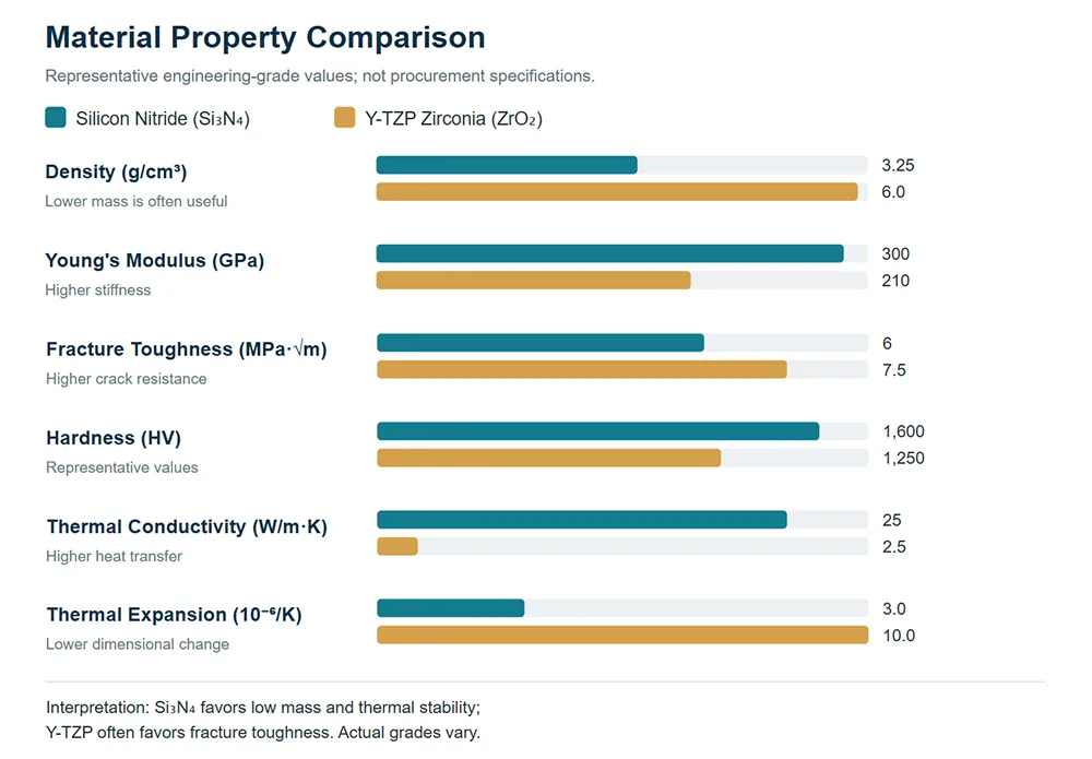
Note: The chart uses illustrative representative values selected from the ranges in Table 1. It is intended to support preliminary material selection, not to replace supplier datasheets or application-specific testing.
6. Main Applications: Where Does Each Material Perform Best?
The most suitable centering pin material depends on the failure mode that engineers need to control. Therefore, application conditions should guide material selection rather than a simple ranking of ceramic properties.
6.1 Silicon Nitride Centering Pin Applications
Semiconductor Equipment
In semiconductor manufacturing equipment, silicon nitride can support precision positioning in selected assemblies that require electrical insulation, low thermal expansion, and resistance to wear. However, engineers must verify particle generation, outgassing requirements, chemical compatibility, and contamination limits for the specific process.
High-Speed Machinery
Because silicon nitride has a relatively low density, it can reduce the mass of moving components. Consequently, engineers may consider it for precision mechanisms, high-speed positioning assemblies, and selected automation equipment where inertia and dimensional stability matter.
High-Temperature Assemblies
Silicon nitride can perform well in selected elevated-temperature environments because it retains useful mechanical properties and exhibits low thermal expansion. Nevertheless, engineers must confirm the actual operating temperature, atmosphere, exposure duration, and grade-specific oxidation behavior.
Aerospace and Precision Systems
In selected aerospace mechanisms and precision systems, silicon nitride may help reduce component mass while maintaining stiffness and thermal stability. Even so, aerospace use requires application-specific qualification, documented traceability, and validation under the relevant environmental and safety requirements.
6.2 Zirconia Centering Pin Applications
Mechanical Locating Fixtures
Zirconia can be suitable for locating fixtures and alignment points that experience repeated contact. In particular, its relatively high fracture toughness can be helpful when the design includes unavoidable local stress concentrations.
Precision Assembly Systems
Precision-ground zirconia pins can locate components in selected assembly systems where stable dimensions and resistance to crack propagation are important. Meanwhile, the mating interface must still avoid excessive interference and damaging edge contact.
Wear-Sensitive Components
Zirconia’s hardness and wear behavior can make it useful in selected sliding or locating contacts. However, the best choice depends on the counterface, lubrication, abrasive particles, and contact pressure rather than hardness alone.
Equipment with Intermittent Contact
When intermittent contact or occasional mechanical disturbance creates a crack-risk concern, zirconia may deserve priority during the initial design review. Nevertheless, designers should calculate impact loads and assess mounting conditions instead of treating zirconia as impact-proof.
6.3 Application-Based Material Selection Table
| Operating Requirement | Initial Material Preference | Reason and Qualification |
|---|---|---|
| Low moving mass | Silicon nitride | Its density is substantially lower than zirconia’s. |
| Low thermal expansion | Silicon nitride | It generally exhibits smaller thermal dimensional changes. |
| Rapid temperature changes | Silicon nitride | Its thermal properties often favor thermal-shock resistance. |
| Crack resistance | Zirconia, often Y-TZP | Transformation toughening can improve fracture toughness. |
| High stiffness at low mass | Silicon nitride | It combines relatively high modulus with low density. |
| Severe impact or shock loading | Evaluate zirconia first, then test | Zirconia may offer higher toughness, but geometry and impact severity remain critical. |
| Electrical insulation | Either material, subject to grade | Verify electrical resistivity and environmental requirements. |
For critical equipment, a practical selection process starts with the expected failure mode and then compares material properties, component geometry, and test results. As a result, engineers can choose the material that best meets the system’s actual requirements instead of relying on a general-purpose ranking.
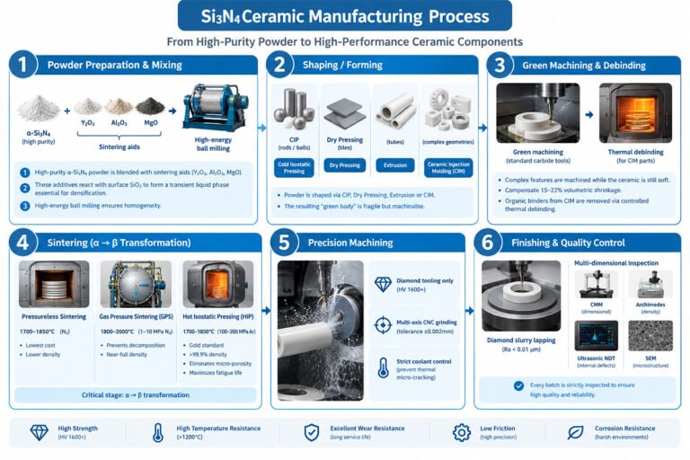
7. Manufacturing Processes for Ceramic Centering Pins
Ceramic centering pins require careful control of powder quality, forming, sintering, machining, and final inspection. Although silicon nitride and zirconia share several manufacturing stages, their powder chemistry, sintering conditions, shrinkage behavior, and final finishing requirements differ.
In both cases, the manufacturer must account for shrinkage during densification and design the green body accordingly. Furthermore, precision grinding and dimensional inspection often determine whether the finished pin can meet its intended tolerance and surface-finish requirements.
7.1 Silicon Nitride Centering Pin Manufacturing
- Powder selection: Select silicon nitride powder with suitable purity, particle size, oxygen content, and sintering characteristics.
- Mixing and additive preparation: Blend the powder with suitable sintering aids and processing additives to support densification and the desired microstructure.
- Forming: Use pressing, cold isostatic pressing, or another suitable forming method to create the pin blank.
- Debinding when required: Remove organic binders according to the selected forming route.
- Sintering: Apply a suitable densification route, such as gas-pressure sintering or another qualified process, to develop the required density and mechanical properties.
- Rough machining: Prepare the sintered blank for final geometry, where the process and stock allowance permit.
- Precision grinding: Use suitable diamond tooling to finish the diameter, length, shoulders, chamfers, and other critical features.
- Final inspection: Check dimensions, straightness, cylindricity, surface finish, and visible defects according to the agreed inspection plan.
- Cleaning and packaging: Protect the finished pins from impact, contamination, and damage during transport.
7.2 Zirconia Centering Pin Manufacturing
- Powder selection: Choose an appropriate zirconia formulation, such as a specified yttria-stabilized grade, according to the required toughness and strength.
- Powder preparation: Control powder dispersion, particle size, stabilizer content, and granulation to achieve consistent forming behavior.
- Forming: Use dry pressing, cold isostatic pressing, injection molding, or another qualified route suitable for the component geometry and production volume.
- Debinding when required: Remove processing binders without introducing unacceptable defects.
- Sintering: Follow a qualified temperature and time profile to achieve the required density and microstructure.
- Precision machining: Grind the pin to its required dimensions, including any stepped diameters, locating shoulders, or end features.
- Surface finishing: Apply the specified finishing operation to achieve the required surface roughness and contact condition.
- Inspection: Verify dimensions, surface quality, and any additional material or performance requirements agreed with the customer.
- Cleaning and packaging: Package the finished parts to preserve dimensional integrity and prevent shipping damage.
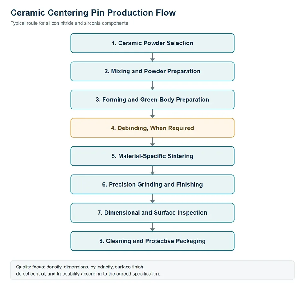
7.3 Manufacturing Process Diagram
The following process diagram summarizes the typical production sequence for both materials. However, manufacturers may adjust individual stages according to the selected ceramic grade, component geometry, required tolerances, and production volume.
7.4 Why Precision Grinding and Inspection Matter
Sintering produces a dense ceramic body, but it does not automatically guarantee the final dimensional accuracy required for a precision pin. Consequently, manufacturers often use diamond grinding to control critical diameters, shoulders, end geometry, and surface quality.
Furthermore, inspection should match the function of the component. A pin used for close-fit positioning may require tighter diameter tolerance and cylindricity control than a pin used only for coarse alignment.
For high-reliability assemblies, the inspection plan may also address surface defects, chipping, cracks, material traceability, and agreed sampling criteria. Therefore, customers should define critical-to-quality features before production begins.
8. AOFE MIMCustom: Custom Ceramic Centering Pin Solutions
Selecting a ceramic centering pin involves more than choosing a raw material. In practice, the supplier must understand the component drawing, the operating environment, the required fit, and the manufacturing controls that determine repeatable performance.
AOFE MIMCustom can work with customers to clarify technical requirements and evaluate custom ceramic component options. For a centering pin project, the following areas provide a useful framework for engineering collaboration.
1. Application-Based Material Selection
First, compare silicon nitride and zirconia against the actual operating conditions. In addition, review temperature, loading direction, impact risk, wear, electrical requirements, and environmental exposure before recommending a material grade.
2. Drawing-Based Customization
Next, define the required diameter, length, stepped features, chamfers, shoulders, and fit requirements from the engineering drawing. Consequently, the supplier can assess the geometry, manufacturing route, and critical dimensional controls before quotation.
3. Manufacturing Route Review
Meanwhile, the forming, sintering, and finishing route should match the material and component geometry. For example, a simple cylindrical pin may follow a different production plan from a pin with narrow shoulders, cross-holes, or complex locating features.
4. Agreed Inspection Criteria
In addition, establish measurable acceptance criteria for critical dimensions, cylindricity, surface finish, and visible defects. Where necessary, request confirmation of available material data, inspection records, and traceability documentation before placing an order.
5. Prototype and Production Coordination
For a new design, begin by reviewing prototype requirements and the critical dimensions that need validation. Subsequently, use test feedback to confirm fit, positioning accuracy, wear behavior, and compatibility with the mating assembly before committing to larger production quantities.
6. Technical Communication
Finally, provide the drawing, target material, operating temperature, load conditions, and annual demand during the inquiry stage. Clear technical information helps AOFE MIMCustom assess feasibility and identify the most important questions before production.
Request a Custom Ceramic Centering Pin Review
Whether your project requires silicon nitride for low mass and thermal stability or zirconia for higher fracture toughness, a clear engineering specification provides the best starting point. Therefore, share your component drawing, preferred material, target tolerances, operating conditions, and quantity requirements with AOFE MIMCustom for a technical review.
Recommended inquiry information: Material grade, pin diameter, overall length, tolerance, surface finish, operating temperature, loading conditions, mating material, and expected order quantity.
Supplier capability note: Confirm material availability, manufacturing processes, achievable tolerances, inspection methods, lead time, certifications, and documentation directly with AOFE MIMCustom. These details should be established for the specific project rather than assumed to apply to every component.
9. Technical Specifications for Custom Ceramic Centering Pins
Custom centering pins can include straight cylindrical bodies, stepped diameters, chamfers, rounded ends, shoulders, and other locating features. However, ceramic machining limits and cost depend on the dimensions, material grade, tolerance, and geometry.
Rather than relying on a generic tolerance range, specify each critical feature on the drawing and ask the supplier to confirm feasibility. In addition, identify the reference surfaces and measurement method so that the supplier and customer evaluate the same characteristics.
| Specification | Information to Define | Why It Matters |
|---|---|---|
| Material | Si₃N₄ or specified zirconia grade | Determines the baseline physical and mechanical properties. |
| Diameter and length | Nominal dimensions and tolerances | Control fit, engagement, and positioning. |
| Geometric accuracy | Cylindricity, straightness, perpendicularity, or runout where relevant | Supports repeatable alignment. |
| Surface finish | Required roughness and finishing condition | Influences friction, contact behavior, and wear. |
| End geometry | Chamfer, radius, flat end, or other profile | Reduces damaging edge contact and eases assembly. |
| Operating conditions | Temperature, load, speed, environment, and contact material | Determines the appropriate material and design. |
| Inspection and documentation | Inspection plan, material data, sampling, and traceability requirements | Establishes measurable acceptance criteria. |
For demanding applications, provide a complete engineering drawing instead of specifying only the nominal diameter. Consequently, the manufacturer can evaluate machining feasibility, dimensional inspection, and the most appropriate production route before confirming the order.
10. Frequently Asked Questions About Ceramic Centering Pins
Q1. Are silicon nitride centering pins better than zirconia pins?
In general, silicon nitride is a strong candidate when low density, stiffness, low thermal expansion, and thermal-shock resistance are priorities. However, zirconia often provides higher fracture toughness, so it may be preferable when crack resistance under mechanical loading dominates the design.
Q2. Which material is lighter, silicon nitride or zirconia?
Silicon nitride is substantially lighter. For example, using representative densities of 3.25 g/cm³ for silicon nitride and 6.0 g/cm³ for zirconia, an identical-volume silicon nitride pin weighs approximately 46% less.
Q3. Which ceramic has higher fracture toughness?
Yttria-stabilized zirconia often has higher fracture toughness than conventional silicon nitride grades because transformation toughening helps resist crack propagation. Nevertheless, actual values depend on the selected material grade and test method.
Q4. Which material is better for high-temperature centering pins?
Silicon nitride often offers advantages in selected high-temperature applications because of its low thermal expansion and relatively high thermal conductivity. However, engineers must check the operating atmosphere, exposure time, temperature range, and grade-specific properties before approving the design.
Q5. Are ceramic centering pins suitable for semiconductor equipment?
Yes, selected silicon nitride and zirconia grades can serve in semiconductor-related equipment. However, the engineer must verify particle generation, chemical compatibility, outgassing, thermal behavior, electrical requirements, and the process-specific contamination limits.
Q6. Can silicon nitride or zirconia centering pins replace metal pins?
Either ceramic may replace a metal pin in a suitably designed application. Nevertheless, the engineer must reassess the fit, contact stress, mounting method, thermal expansion, impact risk, and possible damage during assembly because ceramics behave differently from ductile metals.
Q7. What manufacturing methods do ceramic centering pins require?
Typically, production includes powder preparation, forming, debinding when necessary, sintering, precision grinding, inspection, and packaging. In addition, the manufacturer must adjust process parameters to the selected material and the component’s geometry.
Q8. What information should I provide when ordering custom ceramic centering pins?
Provide the material preference, engineering drawing, nominal dimensions, tolerances, surface-finish requirements, operating temperature, loading conditions, mating material, quantity, and inspection requirements. Consequently, AOFE MIMCustom can review the application and clarify the technical details needed for a quotation.
Q9. Does higher hardness always mean better wear resistance?
No. Although hardness influences abrasive wear, service life also depends on surface finish, contact pressure, lubrication, counterface material, impact, and operating temperature. Therefore, application-specific wear testing provides a more reliable comparison than hardness alone.
Q10. How can I prevent ceramic centering pins from cracking during installation?
First, control the fit and avoid excessive interference. Furthermore, prevent direct hammering, sharp-edge contact, bending loads, and local stress concentrations. Finally, use suitable assembly tooling and verify that the housing tolerances match the ceramic pin’s specifications.
Conclusion: Choose the Material That Matches the Failure Mode
Silicon nitride and zirconia both offer valuable advantages for precision ceramic centering pins, but they solve different engineering problems. Silicon nitride generally provides lower density, higher stiffness, higher thermal conductivity, and lower thermal expansion, making it attractive for lightweight mechanisms and thermally demanding assemblies.
By contrast, zirconia, particularly Y-TZP, often offers higher fracture toughness and can be a better starting point for applications where resistance to crack propagation is especially important. Nevertheless, neither material guarantees superior wear life or impact performance in every design.
For high-speed, low-mass, and temperature-sensitive applications, evaluate silicon nitride first. For designs dominated by fracture-toughness requirements, evaluate zirconia carefully. Ultimately, confirm the decision through material-grade data, drawing review, dimensional inspection, and representative application testing.