Precision Manufacturing | Powder Metallurgy | Metal Forming
Metal Injection Molding and Metal Extrusion Molding Technologies
Metal injection molding (MIM) and metal extrusion are two important manufacturing technologies that transform metal feedstock into precisely engineered components. Although both processes use dedicated tooling to shape metal efficiently, MIM produces three-dimensional parts with complex geometries, whereas extrusion creates long products with a defined cross-sectional profile.
Consequently, engineers can select the appropriate process according to component geometry, material requirements, production volume, dimensional tolerances, and total manufacturing cost.
1. Overview: Two Different Approaches to Metal Forming
In modern manufacturing, miniature components and complex structural profiles often require geometries that conventional machining would produce inefficiently. Therefore, manufacturers use specialized forming processes to reduce material removal, support repeatable production, and create shapes that would otherwise require multiple machining operations.
More specifically, MIM combines fine metal powder with a temporary binder, injects the resulting feedstock into a mold, and then removes the binder before sintering the remaining metal particles into a dense component. By contrast, metal extrusion drives a solid, deformable billet through a shaped die, allowing the metal to emerge as a continuous profile.
Metal Injection Molding (MIM)
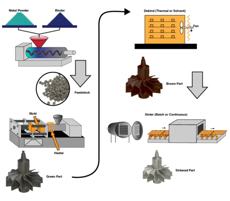
First, the process uses a mold cavity to create a three-dimensional green component from metal powder and binder.
Typical focus: small, complex, repeatable components manufactured in medium-to-high volumes.
Metal Extrusion
Meanwhile, the process forces a solid metal billet through a die to create a long product with a consistent cross-section.
Typical focus: rods, tubes, structural profiles, and complex heat-dissipation sections.
Ultimately, neither technology replaces the other in every situation. Instead, the part’s geometry, material condition, manufacturing volume, and performance requirements determine which approach offers the strongest technical and economic advantage.
2. What Is Metal Injection Molding (MIM)?
Metal injection molding is a near-net-shape manufacturing process that combines powder metallurgy with the high-volume forming principles of plastic injection molding. In this process, fine metal powder supplies the material’s metallic properties, while a temporary binder gives the feedstock enough flowability and cohesion to fill a precision mold.
Unlike conventional plastic injection molding, however, MIM does not retain the polymer binder as the main structural material. Instead, manufacturers remove most of the binder after molding and use high-temperature sintering to bond the metal particles, densify the component, and develop its final properties.
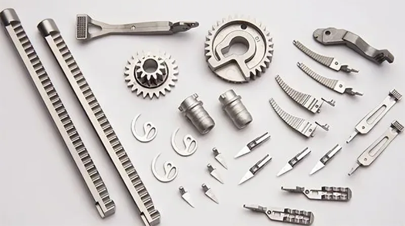
As a result, MIM can produce intricate three-dimensional geometries that combine small dimensions, fine surface details, and difficult features such as grooves, bosses, thin walls, and selected internal or external threads. Nevertheless, actual capability depends on the component geometry, alloy, tooling design, feedstock behavior, and dimensional requirements.
2.1 MIM Manufacturing Process Flow Diagram
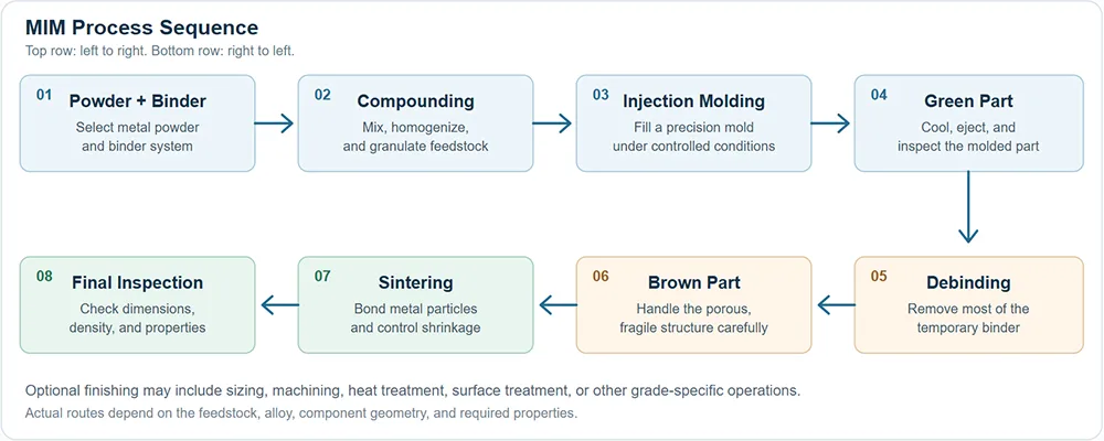
Figure 1. MIM transforms a powder-binder feedstock into a dense metallic component through injection molding, debinding, sintering, and inspection.
2.2 Feedstock Preparation: Engineering a Stable Powder-Binder Mixture
Initially, manufacturers select a metal powder and a binder system that suit the target alloy, component geometry, and sintering route. For example, stainless steel and selected titanium alloys can serve as MIM feedstocks, while other qualified materials may support additional specialized applications.
Typically, MIM uses fine metal powders, often with particle sizes in the tens-of-micrometers range or smaller, although the optimum distribution depends on the alloy and process requirements. Because particle size and shape affect packing density, flow behavior, and sintering activity, powder selection directly influences the consistency of the finished component.
During compounding, heat and mechanical shear distribute the binder throughout the powder, creating a homogeneous material with controlled rheological behavior. Consequently, manufacturers must control powder loading, binder viscosity, mixing conditions, and pellet consistency to limit segregation, trapped air, and nonuniform shrinkage.
2.3 Injection Molding: Forming Complex Three-Dimensional Geometry
Next, the molding machine heats the feedstock into a flowable condition and injects it into a precision mold cavity under controlled pressure. As the feedstock cools or solidifies, the binder holds the metal particles in the required shape and allows the operator to eject a component known as the green part.
At this stage, the green part already contains the intended external shape and many of its detailed features, but the binder still occupies part of its volume. Therefore, the green part remains larger than the final sintered component and generally has limited mechanical strength compared with the finished metal.
Meanwhile, mold filling depends on gate design, venting, feedstock temperature, injection speed, pressure, and component-wall thickness. If these parameters do not work together, the molded part may develop weld lines, short shots, sink marks, trapped-gas defects, or density variations that become more difficult to correct after sintering.
2.4 Debinding: Removing the Temporary Binder
After molding, manufacturers remove most of the binder through a route suited to the feedstock formulation, such as solvent extraction, catalytic debinding, thermal debinding, or a combined process. During this stage, the component develops a network of pores that allows the remaining binder to escape before high-temperature sintering.
Following debinding, the fragile component is often called the brown part, although industry terminology and intermediate-stage definitions can vary by process. Because the binder no longer supports the powder particles to the same extent, operators must handle the part carefully and protect it from bending, impact, or uneven support.
In addition, debinding rate, component thickness, furnace atmosphere, solvent compatibility, and temperature gradients influence the quality of the porous structure. Therefore, excessive heating or incomplete binder removal can lead to internal gas pressure, cracks, distortion, residual carbon, or other defects during subsequent processing.
2.5 Sintering: Developing Density and Mechanical Properties
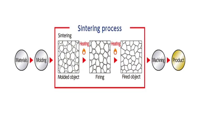
After debinding, a controlled sintering cycle heats the metallic skeleton to a material-specific temperature below its bulk melting point in a suitable atmosphere. During this operation, atomic diffusion forms stronger particle-to-particle bonds, the pores shrink, and the component develops its final density and mechanical properties.
Importantly, sintering also causes substantial dimensional shrinkage as the porous brown part densifies. Depending on the feedstock, solids loading, alloy, and process, linear shrinkage around 15–20% is a useful illustrative range, but some systems can shrink by different amounts; accordingly, manufacturers must calibrate mold dimensions against validated production data.
Furthermore, temperature uniformity, time at temperature, furnace atmosphere, support fixtures, and component geometry affect density, distortion, grain structure, and chemical composition. For this reason, an apparently correct mold design cannot guarantee dimensional accuracy without a stable debinding and sintering process.
2.6 Finishing and Quality Inspection
Once sintering ends, manufacturers inspect the component’s dimensions, surface condition, density, and relevant mechanical or functional properties. Depending on the part, additional operations may include sizing, machining, heat treatment, polishing, coating, or surface finishing.
Ultimately, a qualified MIM process combines repeatable molding with controlled binder removal and sintering, allowing manufacturers to produce consistent components at industrial scale without machining away the majority of the original component volume.
3. Technical Advantages and Limitations of MIM
3.1 Main Advantages
- Complex geometry: MIM can combine numerous geometric features in a single component, reducing the need for separate machining and assembly operations.
- High-volume repeatability: Once manufacturers qualify the mold and the process, automated injection molding can support large production runs with repeatable part geometry.
- Material efficiency: Because the process shapes metal near its final dimensions, it can reduce the cutting waste associated with subtractive machining.
- Material versatility: Qualified feedstocks allow manufacturers to produce components from stainless steels and various other alloys.
- Functional integration: For example, designers can sometimes combine several small features in one MIM component rather than assemble separate parts.
3.2 Important Limitations
- Tooling investment: Precision molds and process development can require significant initial expenditure, especially for complex geometries.
- Shrinkage control: Sintering changes component dimensions, so manufacturers must manage shrinkage, warpage, and dimensional variation carefully.
- Process sensitivity: Powder properties, binder distribution, mold filling, debinding, and furnace conditions all influence final quality.
- Production-volume dependence: For low-volume parts or components with simple geometry, conventional machining or another process may offer lower total cost.
- Size and geometry constraints: Very large components, excessively thick sections, or difficult unsupported features may challenge tool filling, debinding, and sintering uniformity.
Engineering takeaway: MIM is most attractive when a component needs complex three-dimensional geometry, repeatable dimensions, and sufficient production volume to justify tooling and process qualification.
4. What Is Metal Extrusion?
Metal extrusion is a bulk forming process that uses compressive force to push a solid metal billet through a die opening. Because the die defines the product’s cross-sectional shape, the process can produce long lengths of rods, bars, tubes, channels, and complex profiles with consistent cross-sections.
Unlike MIM, extrusion does not depend on removing a temporary binder or sintering a powder-based green part. Instead, the metal deforms plastically under pressure and flows through the die while remaining solid, although manufacturers commonly heat the billet during hot extrusion to reduce deformation resistance and support material flow.
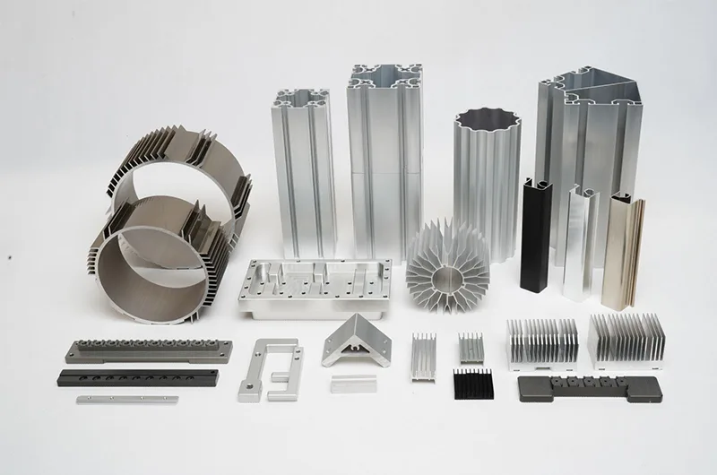
For example, aluminum extrusion can create hollow sections, multiple channels, and thin heat-dissipation fins in a single profile. Similarly, copper and magnesium alloys may suit selected extrusion applications, while other metals require process conditions appropriate to their strength, ductility, temperature range, and tooling limitations.
4.1 Metal Extrusion Manufacturing Process Flow Diagram
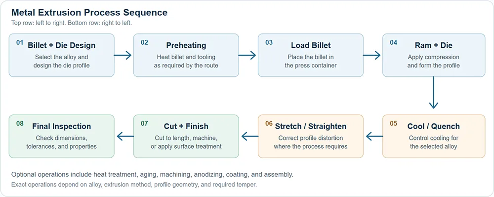
Figure 2. Metal extrusion shapes a solid billet through a designed die, after which controlled cooling, straightening, cutting, and inspection prepare the profile for use.
4.2 Billet Selection and Die Design
Initially, engineers select a billet alloy and define the required cross-sectional geometry, wall thickness, dimensional tolerances, and mechanical properties. Because the die determines the profile’s basic shape, its opening, bearing lengths, support structure, and material flow characteristics strongly affect dimensional consistency and surface quality.
For hollow or multi-channel profiles, specialized dies may use mandrels and internal support features to create the required cavities. Therefore, complex hollow sections demand careful consideration of metal flow, die strength, weld formation in porthole-type tooling, wall-thickness uniformity, and extrusion pressure.
4.3 Billet Heating and Press Preparation
During hot extrusion, manufacturers heat the billet to a temperature that provides sufficient plasticity while remaining below the material’s melting point. For example, aluminum billets commonly operate within an approximate range of 375–500°C, depending on the alloy and process, whereas other metals require different thermal conditions.
Meanwhile, operators may preheat the container and die to limit excessive temperature gradients and support consistent metal flow. Nevertheless, an excessively high billet temperature can increase oxidation, surface defects, or unwanted microstructural changes, so temperature must match the alloy and target properties.
4.4 Extrusion: Plastic Deformation Under High Pressure
Next, the press ram applies compressive force to the billet inside the container, causing the metal to flow toward and through the shaped die opening. Although the ram applies substantial pressure, the metal remains solid in conventional extrusion and undergoes plastic deformation rather than melting.
As the material exits the die, it takes the die-defined cross-section and forms a continuous profile. Consequently, the same extrusion run can produce long sections with repeated fins, channels, grooves, or other shapes that would require extensive machining to create from solid stock.
In practice, billet temperature, die temperature, extrusion ratio, ram speed, lubrication, alloy composition, and die geometry affect press load, metal flow, surface condition, and dimensional stability. Therefore, process engineers monitor these variables to reduce surface tearing, die lines, uneven flow, distortion, and other defects.
4.5 Cooling, Straightening, and Cutting
Following extrusion, the hot profile moves through a cooling stage selected for the alloy and required mechanical properties. Depending on the application, manufacturers may use air cooling, controlled cooling, or quenching, although not every extrusion route needs the same treatment.
After cooling, operators may stretch or straighten the profile to improve straightness, relieve selected residual stresses, and bring the product closer to its specified geometry. Subsequently, saws or other cutting systems divide the continuous extrusion into designated lengths for further processing or assembly.
4.6 Heat Treatment and Finishing
For suitable heat-treatable alloys, solution treatment, quenching, and artificial aging can help achieve the specified temper and mechanical properties. Additionally, manufacturers may machine mounting faces, drill holes, anodize aluminum, apply protective coatings, or complete other operations needed for the finished product.
Finally, inspectors verify profile dimensions, wall thickness, straightness, surface quality, and the relevant material properties against the product specification. Through this combination of die control and downstream processing, extrusion turns a billet into a production-ready continuous profile.
5. Technical Advantages and Limitations of Metal Extrusion
5.1 Main Advantages
- Complex constant cross-sections: Extrusion can form profiles with fins, slots, channels, ribs, and selected hollow geometries through a single die.
- High material utilization: Because the process shapes bulk metal directly, it can reduce the machining waste associated with milling a large profile out of solid stock.
- Long continuous products: A press run can produce profiles much longer than an individual part, after which manufacturers cut them to the required lengths.
- Efficient repetitive production: Once manufacturers qualify the alloy, die, and process parameters, extrusion can produce large quantities of similar profiles.
- Useful property development: Appropriate extrusion and downstream heat treatment can produce mechanical properties suited to structural and functional applications.
5.2 Important Limitations
- Constant cross-section requirement: The basic extrusion process produces a profile whose cross-section remains substantially consistent along its length, although subsequent machining or forming can add further features.
- Die design complexity: Thin walls, small channels, and complicated hollow geometries may require sophisticated tooling and careful flow balancing.
- Material restrictions: Not every alloy offers suitable extrusion behavior, so alloy selection must match the required deformation conditions and properties.
- Dimensional and surface limits: Die wear, temperature variation, metal-flow imbalance, and cooling can introduce dimensional changes or surface defects.
- Downstream processing: Some profiles still require cutting, machining, heat treatment, straightening, or surface finishing before assembly.
Engineering takeaway: Metal extrusion offers a strong solution when a product needs a long, repeatable, relatively constant cross-section with efficient material use.
6. Metal Injection Molding vs. Metal Extrusion: Key Differences
Although MIM and extrusion both use dedicated tooling to improve production efficiency, they solve different shape-making problems. Specifically, MIM targets complex three-dimensional components, while extrusion specializes in long profiles that maintain a consistent cross-section.
| Comparison Factor | Metal Injection Molding (MIM) | Metal Extrusion |
|---|---|---|
| Starting material | Fine metal powder mixed with binder | Solid metal billet |
| Primary forming mechanism | Injection of flowable powder-binder feedstock | Plastic deformation through a die opening |
| Typical geometry | Complex three-dimensional components | Long products with consistent cross-sections |
| Main process stages | Compounding, injection, debinding, sintering | Billet preparation, extrusion, cooling, cutting |
| Dimensional change | Substantial shrinkage during sintering requires compensation | Thermal contraction and process distortion require control |
| Tooling role | Mold cavity defines the component’s three-dimensional shape | Die opening defines the profile cross-section |
| Material efficiency | Near-net-shape forming reduces material removal | Efficient bulk forming; butt ends and trimming may still create scrap |
| Production economics | Often attractive for complex parts produced at sufficient volume | Often attractive for repeated profiles and long production runs |
| Typical applications | Precision gears, miniature housings, medical and electronic components | Heat sinks, structural profiles, tubes, frames, rails |
Therefore, designers should base the process decision on part geometry and production economics rather than assuming that one forming technology offers better performance in every category. In some products, extrusion may create the primary profile, while subsequent machining or other processes generate the final features.
7. Industrial Applications of MIM
Across several industries, MIM supports the manufacture of compact metal components whose complexity, size, or production volume can make conventional machining less attractive. However, each application still requires validation of material compatibility, fatigue behavior, surface finish, tolerance, and regulatory requirements.
7.1 Consumer Electronics
For compact electronic devices, MIM can produce selected precision components such as small gears, camera-related parts, connector components, and other miniature structural features. Consequently, product designers can combine multiple geometric details while reducing the number of separate manufacturing operations.
7.2 Medical and Dental Devices
Within medical and dental manufacturing, qualified MIM materials can support selected instrument components, orthodontic brackets, and precision metal parts used in compact devices. Nevertheless, the chosen material, surface finish, cleaning process, biocompatibility evidence, and sterilization compatibility must satisfy the intended medical application and applicable regulations.
7.3 Automotive and Mechanical Systems
Similarly, manufacturers can use MIM for selected small automotive parts, actuator components, precision linkages, locking mechanisms, and other complex parts, provided that the process meets the component’s strength, fatigue, temperature, and quality requirements.
8. Industrial Applications of Metal Extrusion
Metal extrusion is especially effective when the component requires a long body with a repeated cross-sectional shape. As a result, the process plays an important role in thermal management, structural engineering, transportation, and industrial equipment.
8.1 Heat Sinks and Thermal Management
For electronic cooling, aluminum extrusion can create profiles with multiple fins and channels that increase exposed surface area. Consequently, extruded heat sinks are widely considered for computer cooling, power electronics, LED fixtures, and other thermal-management systems, with performance depending on geometry, alloy, airflow, and interface design.
8.2 Construction and Structural Profiles
In construction, extrusion produces window frames, curtain-wall sections, rails, structural members, and other profiles that integrate ribs, grooves, or hollow spaces. Therefore, designers can combine structural performance, low mass, and functional features within a single elongated section.
8.3 Transportation and Industrial Equipment
Meanwhile, selected extruded profiles support automotive structures, railway equipment, aerospace applications, and industrial machinery, where engineers value the combination of repeatable geometry and efficient material use. Nevertheless, the alloy, temper, structural design, and qualification requirements must match the actual load and service environment.
9. How to Select the Right Manufacturing Process
When engineers compare MIM with extrusion, they should start by defining the component’s geometry, material, required properties, expected production volume, tolerances, and budget. Subsequently, a manufacturing review can determine whether the primary challenge lies in creating complex three-dimensional features or maintaining a consistent cross-section along a long product.
Select MIM When…
The part has a complex three-dimensional shape, multiple fine features, or a geometry that would require several machining or assembly steps.
Also verify that projected production volume can support tooling and process-development costs.
Select Extrusion When…
The product requires a long profile with a constant cross-section, such as a channel, tube, structural member, or multi-fin heat sink.
Additionally, confirm alloy extrudability, die complexity, tolerances, and required downstream operations.
Manufacturing Review Checklist
- First, define the required three-dimensional geometry or constant cross-section.
- Next, confirm the material grade, chemical composition, strength, wear resistance, corrosion resistance, and operating temperature.
- Additionally, establish critical dimensions, tolerances, surface finish, and inspection criteria.
- Meanwhile, evaluate tooling investment, production volume, cycle time, raw-material cost, and expected yield.
- For MIM, validate feedstock flow, mold filling, binder removal, sintering, shrinkage, and final density.
- For extrusion, validate billet and die temperatures, extrusion speed, material flow, cooling, straightness, and final temper.
- Finally, compare the complete manufacturing route rather than the forming operation alone, including secondary machining, finishing, and quality assurance.
10. Frequently Asked Questions
What is metal injection molding?
Essentially, metal injection molding combines fine metal powder with a temporary binder, injects the feedstock into a mold, removes the binder, and then sinters the component. Consequently, the process can create complex three-dimensional metal parts at production volumes that justify precision tooling.
Why does MIM require debinding and sintering?
During injection molding, the binder helps the powder flow and retain the required shape. Afterwards, debinding removes most of that temporary material, while sintering forms stronger metal-particle bonds and develops the density and mechanical properties of the finished part.
How much shrinkage occurs during MIM sintering?
In many MIM systems, linear shrinkage around 15–20% provides an illustrative range, although the actual value depends on powder loading, binder formulation, alloy, and sintering conditions. Therefore, manufacturers must measure shrinkage during process qualification and compensate for it in the mold design.
What is metal extrusion molding?
In metal extrusion, a press pushes a solid, deformable billet through a die opening to create a profile with the required cross-section. As a result, manufacturers can efficiently produce long rods, tubes, channels, frames, and complex heat-sink profiles.
Does metal extrusion melt the billet?
No, conventional metal extrusion uses plastic deformation while the billet remains solid. In hot extrusion, manufacturers heat the billet to improve deformability, but they still keep the metal below its melting point.
Which process is better for miniature precision metal parts?
Generally, MIM is a strong candidate when miniature components combine complex three-dimensional geometry with sufficient production volume. However, machining, micro-forming, or other processes may outperform MIM for particular materials, very tight tolerances, low quantities, or specialized surface requirements.
Which process is more suitable for heat sinks?
For long heat sinks with repeated fins and a constant cross-section, metal extrusion-especially aluminum extrusion-is often a practical option. By contrast, MIM may suit selected small components or complex three-dimensional parts associated with a larger thermal assembly.
Can both processes reduce material waste?
Yes, both processes can improve material utilization relative to machining large volumes from solid stock, although neither eliminates all waste. For example, MIM may generate runners or rejected parts, while extrusion may produce butt ends, trim, and material associated with downstream machining.
Conclusion: Matching Forming Technology to Component Geometry
Overall, metal injection molding and metal extrusion provide different but complementary solutions for precision manufacturing. MIM transforms fine powder and binder into complex three-dimensional parts through injection molding, debinding, and sintering, while extrusion converts solid billets into long profiles through compressive plastic deformation.
Consequently, manufacturers should choose MIM when part complexity and production volume justify the additional powder-processing stages, whereas extrusion often suits products that require long, repeated cross-sections and efficient material use. In either case, process stability, tooling quality, material selection, dimensional control, and inspection determine the final component’s performance.
Ultimately, the most effective manufacturing strategy begins with engineering requirements rather than a preference for a specific technology. By assessing geometry, properties, production volume, tolerances, and total process cost together, engineers can select a forming route that delivers reliable parts and a competitive manufacturing result.
Technical References and Further Reading
For additional technical detail, consult the following professional and industry resources.
- European Powder Metallurgy Association (EPMA): Metal Injection Moulding – MIM process fundamentals, binder removal, and sintering considerations.
- ASM International: One Minute Mentor – Metal Injection Molding – Feedstock, injection, debinding, sintering, and shrinkage overview.
- The Aluminum Association: Processing 101 – Aluminum manufacturing processes, including extrusion.
- Aluminum Extruders Council: Aluminum Extrusion Process – Billet preparation, press operation, cooling, and downstream finishing.
- Handbook of Metal Injection Molding: Debinding and Sintering – Technical discussion of binder removal, sintering, atmosphere, and process control.