Manufacturing Technology / Powder Metallurgy
Introduction to MIM Metal Injection Molding Process
In brief, Metal Injection Molding (MIM) combines fine metal powders, polymer binders, injection molding, debinding, and sintering to produce small, complex metal components at repeatable production volumes.
MIM Process
Precision Metal Parts
Design for Manufacturability
What Is Metal Injection Molding?
Within modern powder metallurgy, Metal Injection Molding (MIM) is a near-net-shape manufacturing process that blends fine metal powder with a carefully selected binder system to create an injectable feedstock. Subsequently, a molding machine forces this heated feedstock into a precision tool, after which debinding removes the binder and sintering bonds the metal particles into a dense component.
Unlike machining, which removes material from a solid workpiece, MIM builds the part close to its final shape and can integrate ribs, grooves, small holes, undercuts, and other detailed features when the tool design allows. As a result, the process can reduce material waste and assembly steps for suitable components, particularly when a project needs repeatable production in medium or high volumes.
Nevertheless, MIM does not suit every metal part; large components, very low order quantities, highly one-off geometries, or features with exceptionally tight tolerances may favor machining, casting, stamping, or metal additive manufacturing. Therefore, engineers should assess geometry, material properties, annual demand, tooling investment, and finishing needs together before selecting a process.
The Four Main Stages of the MIM Process
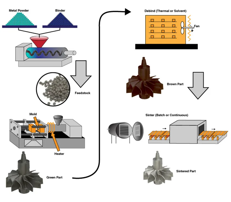
Broadly, manufacturers divide the Metal Injection Molding process into four connected stages: feedstock preparation, injection molding, debinding, and sintering. Meanwhile, quality checks and optional secondary operations link these stages so the finished part meets the drawing, material, and application requirements.
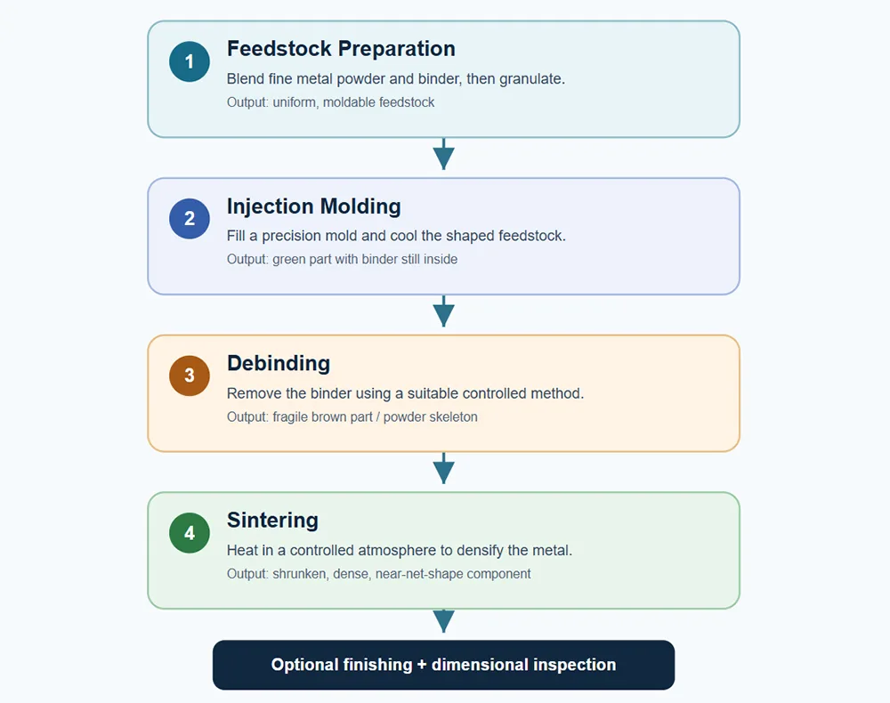 Figure 1. Typical Metal Injection Molding workflow. Actual feedstock chemistry, debinding route, sintering profile, shrinkage, and finishing requirements depend on the selected alloy and part design.
1. Feedstock Preparation and Granulation
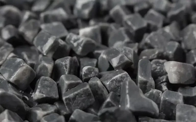
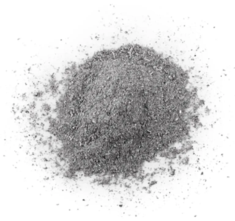
To begin, process engineers select a metal powder with suitable chemistry, particle characteristics, and size distribution, then combine it with a binder that gives the mixture enough flow for injection. At this stage, controlled heating and mixing help distribute the binder throughout the powder, while granulation creates consistent pellets for stable feeding and molding.
Because powder loading and binder formulation affect flow, green strength, debinding behavior, and final shrinkage, manufacturers treat feedstock consistency as a foundational quality variable. Consequently, poor mixing or an unsuitable formulation can cause filling defects, dimensional variation, or downstream cracking.
2. Injection Molding
During injection molding, a heated barrel softens the feedstock and a screw or plunger drives it through the gate system into the mold cavity. Once the material fills and cools, the tool releases a shaped component known as the green part, which still contains most of its original binder.
Thereafter, tool design, gate position, venting, injection settings, cooling, and ejection all influence green-part consistency. Balanced wall sections and well-planned transitions, for example, can reduce the risk of incomplete filling, weld-line issues, sink marks, or deformation during later processing.
3. Debinding
Following molding, debinding removes the binder in a controlled sequence so the metal particles retain the required geometry. Depending on the binder system, manufacturers may use solvent, catalytic, water-based, thermal, or combined debinding routes; each route requires a matching process window and suitable environmental controls.
Since the component loses much of its binder before it gains sintered strength, the resulting brown part can be fragile and needs careful handling. Limiting internal pressure, cracks, distortion, or residue requires engineers to control extraction rate, temperature, gas flow, and part support.
4. Sintering
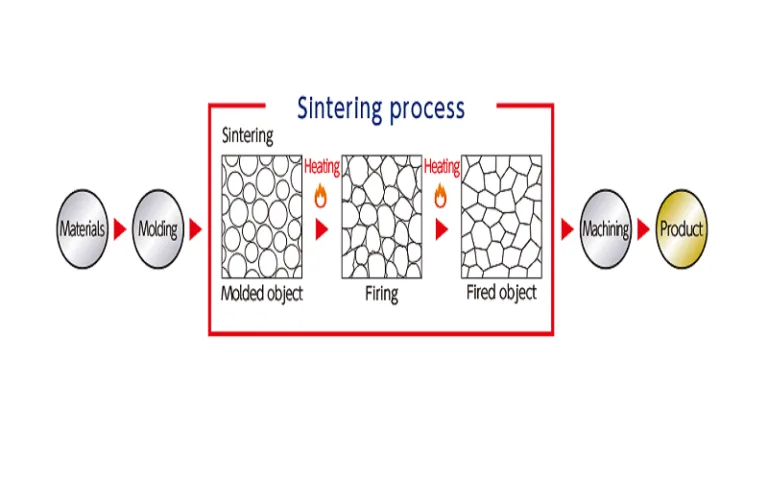
Finally, the furnace heats the debound part under an alloy-appropriate atmosphere and temperature profile, allowing diffusion to bond the metal particles and reduce porosity. Densification causes substantial component shrinkage; many MIM systems exhibit shrinkage in the broad range of roughly 15% to 22%, although the actual value varies with feedstock, alloy, tooling, and furnace conditions.
Accordingly, engineers compensate for expected shrinkage in the mold design and validate dimensions through trials and statistical process control. When the drawing requires tighter tolerances or specific surface properties, the production route can add sizing or coining, CNC machining, grinding, heat treatment, polishing, passivation, coating, or other approved finishing operations.
Key Advantages of Metal Injection Molding
Complex Geometry
With suitable designs, MIM forms intricate three-dimensional features in one molded component, which may reduce assembly and multi-step machining.
Repeatable Production
Upon validation, multi-cavity molds and process controls and process controls can support consistent medium- to high-volume output.
Material Efficiency
Given that MIM creates near-net-shape parts, it can reduce machining chips compared with routes that remove large amounts of stock, although runners and process scrap still require management.
Broad Alloy Options
Subject to supplier capability, MIM can process stainless steels, low-alloy steels, tool steels, titanium alloys, copper-based alloys, and selected specialty materials.
Nonetheless, MIM requires upfront tool investment and careful control of binder removal and sintering; therefore, its commercial value depends on part complexity, required properties, annual quantity, dimensional tolerances, and the cost of any secondary operations.
Common Materials for MIM Components
Material selection should account for corrosion exposure corrosion exposure, strength, hardness, wear, magnetic behavior, thermal requirements, and any industry-specific qualification. Among widely used options are MIM 316L and 17-4 PH stainless steel, while other grades may be available from qualified suppliers.
| Material family | Typical selection focus | Examples of potential use |
|---|---|---|
| Austenitic stainless steel | Corrosion resistance and general-purpose performance | Consumer, fluid-handling, and selected medical-device components |
| Precipitation-hardening stainless steel | Strength and heat-treatable performance | Latches, mechanisms, and precision structural parts |
| Low-alloy and tool steels | Strength, hardness, or wear resistance according to grade and treatment | Tooling-related parts, gears, locking features, and wear components |
| Titanium and specialty alloys | Specific strength, corrosion, thermal, or functional requirements | Selected medical, aerospace, and specialized engineering parts |
| Copper-based and magnetic alloys | Electrical, thermal, or magnetic performance | Electrical and functional components, where the alloy is supported by the process |
Note: The table gives examples rather than a guarantee of availability. Confirm material grade, heat-treatment route, required properties, and applicable standards with the selected MIM supplier.
Applications of Metal Injection Molding
Across sectors, MIM serves industries that need detailed geometry and repeatable production multiple sectors that need compact metal components with functional features. Still, each application requires material validation, dimensional checks, and any necessary regulatory qualification.
Consumer Electronics and Telecommunications
For compact assemblies, MIM can produce hinges, brackets, camera-related rings, connector elements, and other small components whose geometry and repeatability matter.
Medical and Dental Devices
Validated alloys and finishing can help MIM support surgical instruments, dental components, and selected reusable or implant-related parts that meet the relevant material and regulatory requirements.
Automotive and Mobility
Automotive mechanisms and subsystems may use MIM for locking elements, seat or latch parts, sensor-related components, and selected functional pieces when they meet load and durability demands.
Hand and Power Tools
Hand-tool mechanisms can use the process to form small complex levers, pawls, locking parts, and wear-related components, subject to the chosen alloy and heat-treatment plan.
Aerospace and Specialized Engineering
Under qualified aerospace production controls, MIM offers geometry flexibility; nevertheless, demanding aerospace applications require rigorous traceability, process qualification, and verification against the applicable specification.
Watches, Consumer Products, and Precision Mechanisms
Decorative products with compact moving parts can also benefit from MIM and finishing options such as polishing or coating intricate shapes with post-processing options such as polishing, coating, or other surface treatments.
MIM Design and Quality Considerations
Before tooling begins, a design-for-manufacturability review should examine the full process chain rather than the CAD model alone. Specifically, engineers should review wall-thickness balance, abrupt section changes, draft and gate layout, undercuts, ejection, support during sintering, predictable shrinkage, and access for inspection or finishing.
- Initially, define critical-to-quality dimensions, datum structure, and the inspection method before setting tolerances.
- Additionally, keep wall thickness as consistent as practical and use suitable radii to support filling and reduce stress concentration.
- Assess shrinkage and warpage risk with the actual alloy, binder, tool, and sintering support plan.
- Ultimately, the final check should confirm whether the part needs machining, heat treatment, surface finishing, or material testing to satisfy its end-use specification.
A useful RFQ package includes a 2D drawing, a 3D CAD model, target alloy, annual demand, expected service environment, critical dimensions, finish requirements, and any required inspection or certification documents. This information helps the supplier judge feasibility and cost drivers before committing to a production route.
How AOFE MIMCustom Supports Custom Part Development
AOFE MIMCustom focuses on Metal Injection Molding (MIM), Ceramic Injection Molding (CIM), and mold and design support. That combination helps customers review the part geometry, material choice, tooling concept, and production route early in the development process.
Further, sharing CAD data, drawings, target quantities, operating conditions, and critical dimensions at the quotation stage makes it easier to assess manufacturability and identify features that may need design adjustment or secondary machining. Moreover, early communication about tolerances, finish, and inspection expectations helps align the part specification with the intended process.
Frequently Asked Questions About Metal Injection Molding
What are the four main steps in MIM?
Typically, manufacturers prepare and granulate the metal-powder feedstock, inject it into a mold, remove the binder through debinding, and sinter the part to achieve densification. Post-sintering, manufacturers may add finishing and inspection steps to meet the drawing.
Which parts benefit most from Metal Injection Molding?
By design, MIM suits relatively small, intricate metal components that require repeatable medium- to high-volume production. Yet, annual quantity, alloy price, tooling cost, geometry, and required post-processing determine whether MIM beats machining or another forming process for a specific project.
Which metals can manufacturers process by MIM?
Typical choices include stainless steels such as 316L and 17-4 PH, along with selected low-alloy steels, tool steels, titanium alloys, copper alloys, and specialty materials. Supplier availability and performance, however, depend on the feedstock, furnace capability, and qualification scope.
Why does a MIM part shrink during sintering?
Throughout sintering, diffusion brings adjacent metal particles together and reduces porosity, so the component becomes denser and smaller. Tool dimensions must therefore account for expected shrinkage, and process validation must confirm the finished part’s dimensional stability.
Does every MIM component need secondary machining?
Not every component requires extra machining; many parts can meet their requirements in a near-net-shape condition, while critical bores, datum surfaces, threads, or tight-tolerance features may need machining or sizing. The drawing and inspection plan should therefore determine the finishing route rather than assuming that every component needs extra processing.
Conclusion
Taken together, Metal Injection Molding offers a practical way to combine complex geometry, material choice, and repeatable production for suitable small precision metal parts. Through integrated control of feedstock preparation, molding, debinding, and sintering, manufacturers can improve consistency and reduce unnecessary downstream work; however, a sound decision still depends on design-for-manufacturability, validated process capability, and total lifecycle cost.
Technical References
Additional technical background is available from the following industry and technical sources:
- Process Overview from the Metal Injection Molding Association (MIMA) – overview of feedstock preparation, molding, debinding, sintering, and secondary operations.
- Materials Range from the Metal Injection Molding Association (MIMA) – examples of alloys and material families used in MIM.
- Dehghan-Manshadi et al., “Metal injection moulding of surgical tools, biomaterials and medical devices: A review,” Powder Technology (2020) – review of MIM applications in medical and biomedical fields.
- ASTM B883: Standard Specification for Metal Injection Molded (MIM) Materials – reference for specified ferrous MIM material grades; confirm the applicable current edition for project requirements.