Materials Engineering · Advanced Ceramics · Manufacturing
7 Methods for Enhancing Toughness with Silicon Nitride and Their Applications
In demanding engineering environments, silicon nitride ceramics combine high strength, low density, wear resistance, and thermal-shock performance; however, their inherent brittleness still requires careful control. Accordingly, this technical guide explains seven silicon nitride toughening methods, shows how each method slows crack growth, and connects the mechanisms with practical applications and manufacturing considerations.
Fracture toughness
Ceramic design
Industrial applications
At a glance: what are the seven toughening methods?
In brief, engineers can improve the crack resistance of silicon nitride by changing its particles, adding a transformable second phase, introducing fibers or nanotubes, controlling its grain shape, or designing a layered structure. Each route works differently; therefore, the best option depends on temperature, atmosphere, load, component geometry, process capability, and cost.
Why Does Silicon Nitride Need Toughening?
Among advanced non-oxide ceramics, silicon nitride (Si₃N₄) stands out because it combines high specific strength, low density, good thermal-shock resistance, strong wear performance, and useful oxidation and chemical resistance. However, its strong covalent bonding also limits plastic deformation, so a sharp flaw can concentrate stress and trigger fast fracture rather than the yielding that often occurs in metals. Consequently, material designers focus on fracture toughness and flaw tolerance as well as hardness, stiffness, and flexural strength. [1]
As a result, in a toughened microstructure, a growing crack may change direction, encounter a compressive stress field, become bridged by a reinforcement, or spend energy pulling a fiber or nanotube out of the matrix. As a result, the material can resist crack propagation more effectively, although the measured benefit still depends on density, grain-boundary phases, defect population, interface bonding, and processing history. [2]
How Toughening Mechanisms Slow a Crack
For a quick visual comparison, the following schematic shows four representative mechanisms: particle-driven crack deflection, stress-induced transformation, reinforcement bridging and pull-out, and crack redirection through a layered design. Meanwhile, self-reinforced grains and carbon-based reinforcements use related bridging, deflection, and pull-out mechanisms at different structural scales.
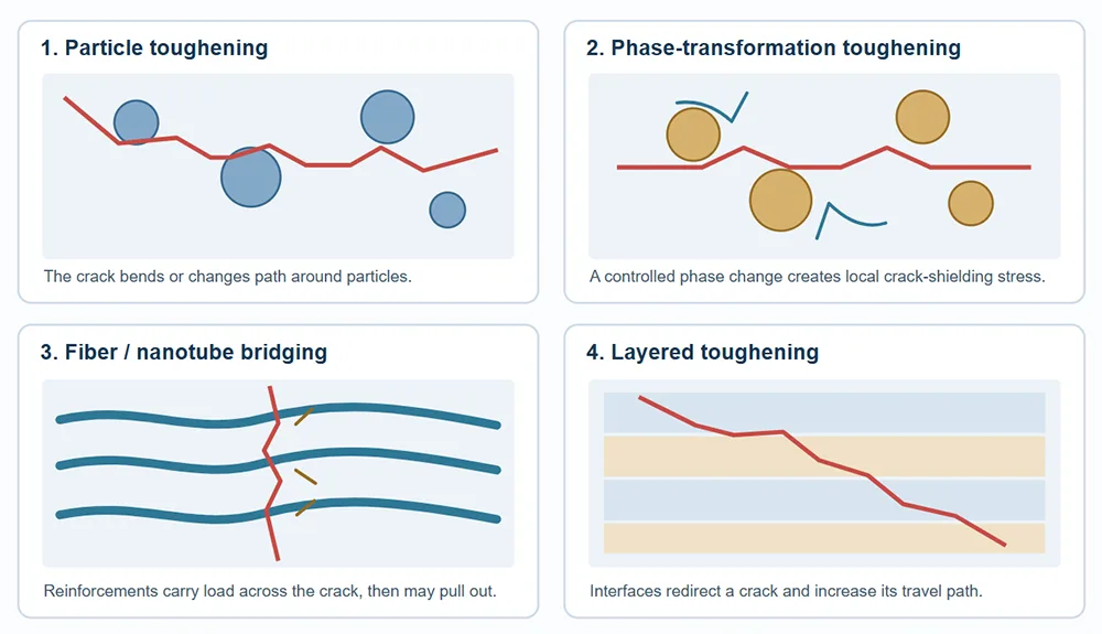 Figure 1. Conceptual illustration only; the actual microstructure and crack path depend on material composition, processing, interface design, and loading conditions.
1. Particle Toughening
First, particle toughening disperses selected hard or high-modulus particles throughout the silicon nitride matrix; common research examples include silicon carbide (SiC), titanium carbide (TiC), and titanium nitride (TiN). Instead of allowing a crack to move along one easy path, well-dispersed particles can deflect the crack, pin its front, or create local stress fields that make continued growth more difficult. Consequently, the outcome depends on particle size, volume fraction, distribution, interfacial bonding, and the porosity left after sintering. [3]
In contrast to a single universal recipe, each particle system involves trade-offs between toughness, hardness, thermal behavior, and manufacturability. For example, agglomerated particles or weak interfaces may introduce defects rather than useful crack resistance; therefore, dispersion and process control matter as much as the additive itself.
Potential applications
Wear-resistant parts, selected cutting-tool grades, and structural components that need a balance of hardness and crack resistance.
Key design check
Verify additive compatibility, particle dispersion, sintered density, and the final strength–toughness balance.
2. Phase-Transformation Toughening
Next, transformation toughening introduces a controlled second phase, often zirconia (ZrO₂), whose metastable tetragonal particles can transform to the monoclinic phase under a crack-tip stress field. Because this transformation produces a local volume expansion and associated strain, the surrounding matrix develops crack-shielding stresses that can reduce the effective driving force for crack growth. [4]
However, the mechanism only works when the zirconia phase remains sufficiently stable during manufacturing and service; uncontrolled transformation can instead cause microcracking or dimensional problems. Moreover, very high temperatures, stabilizer content, particle size, and the chemistry of the silicon nitride matrix can change the response, so engineers must validate this route for the target operating environment rather than assume a fixed toughness increase.
Potential applications
Selected wear parts, seals, and structural components where a controlled second phase can improve crack resistance without compromising service stability.
Key design check
Confirm phase stability, thermal limits, residual stresses, and dimensional stability across the full temperature cycle.
3. Continuous-Fiber Toughening
Meanwhile, continuous-fiber toughening combines a silicon nitride matrix with long reinforcing fibers, such as silicon carbide fibers or carbon fibers, to create a ceramic-matrix composite. As a crack approaches a fiber, the interface may guide the crack around the reinforcement; after the crack crosses the matrix, fibers can bridge the opening and dissipate energy through controlled debonding, friction, and pull-out. [5]
In practice, fiber reinforcement requires more than simply adding fibers to a ceramic powder. In addition, engineers must manage fiber alignment, matrix infiltration or forming, interface coatings when needed, densification, and thermal-expansion mismatch; otherwise, the process can damage fibers or create harmful pores. Accordingly, the route usually suits specialized high-performance composites better than low-cost, simple-shape ceramic parts.
Potential applications
Specialized thermal-structural components, high-temperature composite structures, and parts that need greater damage tolerance than a monolithic ceramic can provide.
Key design check
Evaluate fiber survival during processing, interfacial shear strength, oxidation exposure, and manufacturing cost.
4. In-Situ Self-Reinforcement
To create a self-reinforced microstructure, manufacturers develop elongated β-Si₃N₄ grains directly inside the silicon nitride matrix by controlling the starting powder, sintering additives, temperature, and time. These rod-like grains can bridge cracks, pull out or debond in a controlled way, and force a crack to follow a more tortuous route; therefore, the ceramic gains toughening mechanisms without relying on a separate continuous-fiber architecture. [2, 3]
Importantly, grain growth must remain controlled because excessive coarsening or incomplete densification can undermine strength and consistency. Therefore, by balancing grain aspect ratio, grain-boundary chemistry, and final density, manufacturers can tune the combination of fracture toughness, flexural strength, wear resistance, and reliability for a particular component.
Potential applications
High-performance bearing elements, cutting tools, wear parts, and structural components that benefit from elongated β-Si₃N₄ grains.
Key design check
Control grain morphology and sintering conditions while checking density, strength scatter, and surface-finishing requirements.
5. Layered Toughening
Moreover, inspired by layered biological materials such as nacre, engineers can arrange ceramic layers with deliberately different compositions, stiffnesses, or interface properties. Rather than letting a crack run straight through the full component, a well-designed interface can make it turn, branch, bridge, or propagate along a longer path; as a result, the crack consumes more energy before it causes complete failure.
Nevertheless, a layered design succeeds only when the layers work together under real service conditions. In particular, designers must account for interlayer bonding, differential shrinkage during firing, thermal-expansion mismatch, residual stress, and the risk of delamination; otherwise, the interfaces may become failure origins instead of protective barriers.
Potential applications
Specialized thermal-shock-resistant structures, wear plates, and engineered ceramic components where layered manufacturing is practical.
Key design check
Test interfacial integrity, firing distortion, thermal cycling, and crack behavior through the complete layered section.
6. Carbon-Fiber Reinforcement
As a material-specific branch of fiber reinforcement, carbon-fiber toughening uses high-specific-strength, low-density fibers to dissipate fracture energy through bridging, debonding, and pull-out. In a silicon nitride composite, however, the fiber–matrix interface determines whether the fibers transfer useful loads or simply behave as defects; therefore, manufacturers must design the interface and firing route together. [5]
Unlike silicon carbide fibers, carbon fibers also face a major limitation in oxidizing high-temperature environments because carbon can oxidize and lose its reinforcing role. Consequently, a carbon-fiber system may suit protected, controlled, or specially engineered environments, while an exposed oxidizing service condition can require a different reinforcement or a suitable environmental protection strategy.
Potential applications
Research-grade ceramic-matrix composites, protected high-temperature structures, and designs where low mass and fiber pull-out are valuable.
Key design check
Assess oxygen exposure, fiber degradation during processing, interface behavior, and long-term retention of composite properties.
Technical distinction: carbon-fiber reinforcement and general continuous-fiber toughening share many mechanisms; this separate section highlights carbon fiber’s specific interface and oxidation constraints rather than implying a wholly different physical principle.
7. Carbon-Nanotube Toughening
At this smaller scale, carbon nanotubes (CNTs) can act as very slender reinforcements inside a silicon nitride matrix. When a crack reaches a suitably dispersed nanotube, the tube may bridge the crack, deflect its path, or pull out against interfacial friction; consequently, these nanoscale processes can absorb energy and improve resistance to crack growth. Research on CNT-reinforced silicon nitride has specifically reported crack bridging and CNT pull-out as important mechanisms. [2]
Even so, CNTs do not guarantee a tougher ceramic simply because their intrinsic strength is high. Agglomeration, poor dispersion, weak or overly strong interfaces, processing damage, porosity, and changes in electrical or thermal behavior can all influence the final result; therefore, repeatable performance requires careful powder mixing, interface control, and consistent densification. [2]
Potential applications
Advanced wear-resistant composites and specialized multifunctional ceramic systems where nanoscale reinforcement justifies added process complexity.
Key design check
Measure CNT distribution, porosity, interface quality, batch-to-batch consistency, and the property trade-offs introduced by carbon.
Comparison of the Seven Silicon Nitride Toughening Methods
To support early material selection, the table below compares each route by its dominant mechanism and practical watch-outs. Nevertheless, it is a screening guide rather than a guaranteed performance ranking, because composition and processing can change outcomes substantially.
| Method | Main toughening mechanism | Possible application fit | Main engineering concern |
|---|---|---|---|
| Particle | Crack deflection, pinning, and local stress fields | Wear parts and selected cutting-tool grades | Dispersion, interface, density, and hardness–toughness balance |
| Phase transformation | Transformation strain and crack shielding | Selected wear and structural components | Phase stability and temperature-dependent behavior |
| Continuous fiber | Crack bridging, deflection, debonding, and pull-out | Specialized high-performance ceramic composites | Fiber alignment, interface engineering, processing cost |
| Self-reinforcement | Elongated β-Si₃N₄ grains bridge and redirect cracks | Bearings, cutting tools, and wear-resistant parts | Grain morphology and sintering control |
| Layered | Crack redirection, branching, and interface energy dissipation | Specialized thermal-shock and wear structures | Interlayer bonding, shrinkage, and delamination |
| Carbon fiber | Fiber bridging, interfacial debonding, and pull-out | Protected or specialized composite structures | Oxidation resistance and fiber–matrix compatibility |
| Carbon nanotube | Nanoscale crack bridging, deflection, and pull-out | Advanced or research-oriented composites | Dispersion, agglomeration, interface, and repeatability |
Where Toughened Silicon Nitride Can Be Used
Beyond laboratory fracture tests, toughening matters when a real component faces repeated contact, vibration, thermal cycling, corrosion, or accidental impact. Accordingly, the following application groups show where silicon nitride’s base properties-and, where justified, a tougher microstructure-can be useful. [1, 6]
Aerospace and High-Temperature Systems
For selected hot or high-speed systems, silicon nitride’s low density, wear resistance, and thermal-shock performance can be attractive; however, actual use depends on grade, atmosphere, temperature, stress, and qualification requirements.
Examples: selected engine accessory parts, high-temperature wear components, and ceramic bearing elements; turbine hot-section designs require specific engineering validation rather than a blanket assumption of suitability.
Bearings and Mechanical Engineering
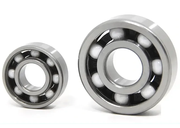
Because silicon nitride offers low density, high stiffness, wear resistance, and good rolling-contact performance, engineers use it in ceramic balls and rollers, especially in hybrid bearings that pair ceramic rolling elements with steel races. As a result, these designs can reduce centrifugal loading in high-speed bearings, although lubrication, contact stress, fit, and surface finish remain critical. [7]
Examples: high-speed machine-tool spindles, selected pump bearings, and precision motion systems.
Seals, Valves, and Corrosive Wear Parts
Likewise, in abrasive or chemically aggressive services, silicon nitride may offer an alternative to metal components that suffer from corrosion or rapid wear. Nevertheless, engineers should verify compatibility with the actual fluid, temperature, pressure, impact load, and mating material before specifying a ceramic seal ring or valve component.
Examples: selected mechanical seal faces, valve wear inserts, and abrasion-resistant parts.
Fine Grinding and Milling Media
In high-purity powder processing, silicon nitride grinding media can limit media wear and reduce contamination compared with less compatible milling materials. Therefore, the chosen grade should match the powder chemistry, milling energy, particle-size target, and allowable impurity level.
Examples: selected ceramic milling balls and wear-resistant grinding components.
High-Speed Ceramic Cutting Tools
Silicon nitride-based cutting-tool grades suit many cast-iron machining operations because they combine hot hardness, wear resistance, and thermal-shock performance. Even so, the insert geometry, workpiece alloy, interrupted-cut severity, coolant strategy, and cutting parameters determine the useful tool life and productivity.
Examples: high-speed turning and selected roughing or finishing of cast iron.
Precision and Custom Ceramic Components
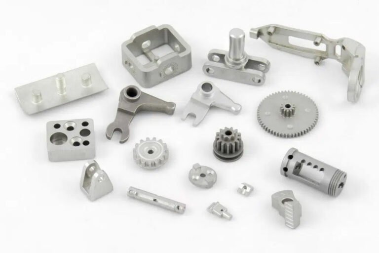
When parts have complex contours or integrated features, the manufacturing route can be as important as the material composition. Consequently, designers should consider whether pressing, machining, ceramic injection molding, or another forming route can meet geometry, tolerance, surface-finish, and volume requirements.
Examples: custom wear inserts, intricate small ceramic parts, and application-specific components after process validation.
How to Select a Silicon Nitride Toughening Strategy
Before selecting an additive or microstructure, engineering teams should define the service environment and the dominant failure mode. In particular, consider these decision points during material development and supplier discussions:
- Operating temperature and atmosphere: First establish the continuous and peak temperatures, oxygen availability, thermal-cycle rate, and chemical exposure, because these conditions can rule out otherwise attractive reinforcements.
- Loading and failure mode: Next distinguish rolling contact, sliding wear, bending, impact, thermal shock, and sustained load; each failure mode calls for a different balance of strength and fracture toughness.
- Geometry and manufacturing route: Meanwhile, assess wall thickness, holes, ribs, undercuts, dimensional tolerance, surface finish, and the amount of post-sinter machining required.
- Microstructure and defect control: In addition, set requirements for density, grain morphology, additive dispersion, interface quality, and acceptable defect populations.
- Validation and cost: Finally, compare material data with component-level testing, inspection requirements, yield, repeatability, and total manufacturing cost instead of relying on a single toughness value.
Ultimately, the strongest design is not always the one with the highest reported fracture toughness; rather, it is the design that consistently meets the actual performance, dimensional, lifetime, and cost requirements.
How AOFE MIMCustom Can Support Custom-Part Development
From a manufacturing perspective, AOFE MIMCustom’s service focus on Ceramic Injection Molding (CIM), Metal Injection Molding (MIM), and mold and design support offers a practical starting point for discussing part geometry, tooling, and process selection together. Moreover, early design-for-manufacturing review can help teams identify features that may affect mold filling, shrinkage allowance, debinding, sintering distortion, and final dimensional control.
For silicon nitride specifically, however, buyers should confirm the supplier’s Si₃N₄ feedstock, ceramic-specific process experience, achievable tolerances, quality controls, and representative application data before treating CIM as a production-ready option. In addition, MIM is a metal process and should not be confused with CIM, which processes ceramic feedstocks; the suitable route depends on material, geometry, production volume, and qualification needs.
Recommended RFQ information: part drawing or 3D model, target material and grade, annual volume, critical dimensions, surface-finish needs, operating environment, and relevant performance tests.
Frequently Asked Questions
What is the most common way to improve silicon nitride fracture toughness?
In many engineering Si₃N₄ grades, controlled growth of elongated β-Si₃N₄ grains provides useful self-reinforcement through crack bridging, deflection, and pull-out. However, the best route depends on the target application, and particle additions or composite reinforcement may fit other requirements better.
Does adding carbon nanotubes always make silicon nitride tougher?
No, because CNT effectiveness depends on dispersion, interface strength, porosity, and damage during processing. Therefore, test data from the actual composite and manufacturing route should guide a design decision.
Can toughened silicon nitride operate at very high temperatures?
Certain silicon nitride grades retain useful properties at elevated temperatures, but performance changes with temperature, atmosphere, duration, microstructure, and grain-boundary chemistry. Consequently, engineers should use grade-specific data and test the full service cycle rather than treat one temperature figure as universal.
Which applications benefit most from silicon nitride ceramics?
Typically, applications that value low density, wear resistance, stiffness, thermal-shock resistance, and chemical stability are strong candidates, including selected bearings, cutting tools, grinding media, seals, and hot or wear-resistant components. Still, component-level testing must confirm the choice for every specific environment.
Is ceramic injection molding suitable for every silicon nitride part?
Not necessarily, because CIM suitability depends on feedstock availability, part size and geometry, wall-thickness variation, shrinkage, tolerances, production volume, and supplier experience with the specific ceramic. Accordingly, confirm Si₃N₄-specific capability and process data during the design review or RFQ stage.
Conclusion
In summary, the seven methods for enhancing toughness with silicon nitride-particle additions, phase-transformation toughening, continuous fibers, self-reinforced grains, layered structures, carbon fibers, and carbon nanotubes-offer different routes to slow crack growth and manage fracture energy. Nevertheless, each route introduces its own processing demands and performance trade-offs, so the choice must reflect the operating environment and the component design.
Ultimately, for reliable engineering results, combine an appropriate toughening mechanism with controlled raw materials, validated forming and sintering, suitable finishing, and application-specific testing. As a result, silicon nitride can deliver its benefits more predictably in demanding wear, precision-motion, machining, and selected high-temperature applications.
Technical References
For additional technical context, the following review articles and research sources discuss silicon nitride structure, applications, second-phase toughening, and carbon-based reinforcement.
- “Silicon Nitride Ceramics: Structure, Synthesis, Properties, and Biomedical Applications,” Materials (2023). Read the review.
- “Silicon Nitride-Based Composites with the Addition of CNTs-A Review of Recent Progress, Challenges, and Future Prospects,” Materials (2020). Read the review.
- “Second phase toughened silicon nitride ceramics: Research progress in toughening mechanism and microstructure design,” Progress in Natural Science: Materials International (2026). Read the review.
- “Transformation Toughening in Zirconia-Containing Ceramics,” Journal of the American Ceramic Society. Read the article.
- “Fiber pullout processes and mechanisms of a carbon fiber reinforced silicon nitride ceramic composite,” Journal of Materials Research. Read the research paper.
- “Silicon Nitride: What it is & Where it’s Used,” Saint-Gobain Ceramic Materials. Read the technical overview.
- “Rolling contact silicon nitride bearing technology: a review of recent research,” Wear (2000). Read the bearing review.