Custom Tooling · Engineering · OEM Development
Custom Mold Design and Development for Plastic, Metal, and Ceramic Injection Molding
For manufacturers developing complex components, a well-designed mold helps establish a practical foundation for part quality, process consistency, and repeat production. Therefore, AOFE MIMCustom approaches mold development by considering part geometry, material behavior, manufacturing conditions, and final inspection requirements together.
Whether your project involves plastic injection molding, metal injection molding (MIM), or ceramic injection molding (CIM), early engineering review helps identify tooling risks before production investment increases.
Mold Engineering at a Glance
What Does Mold Design and Development Include?
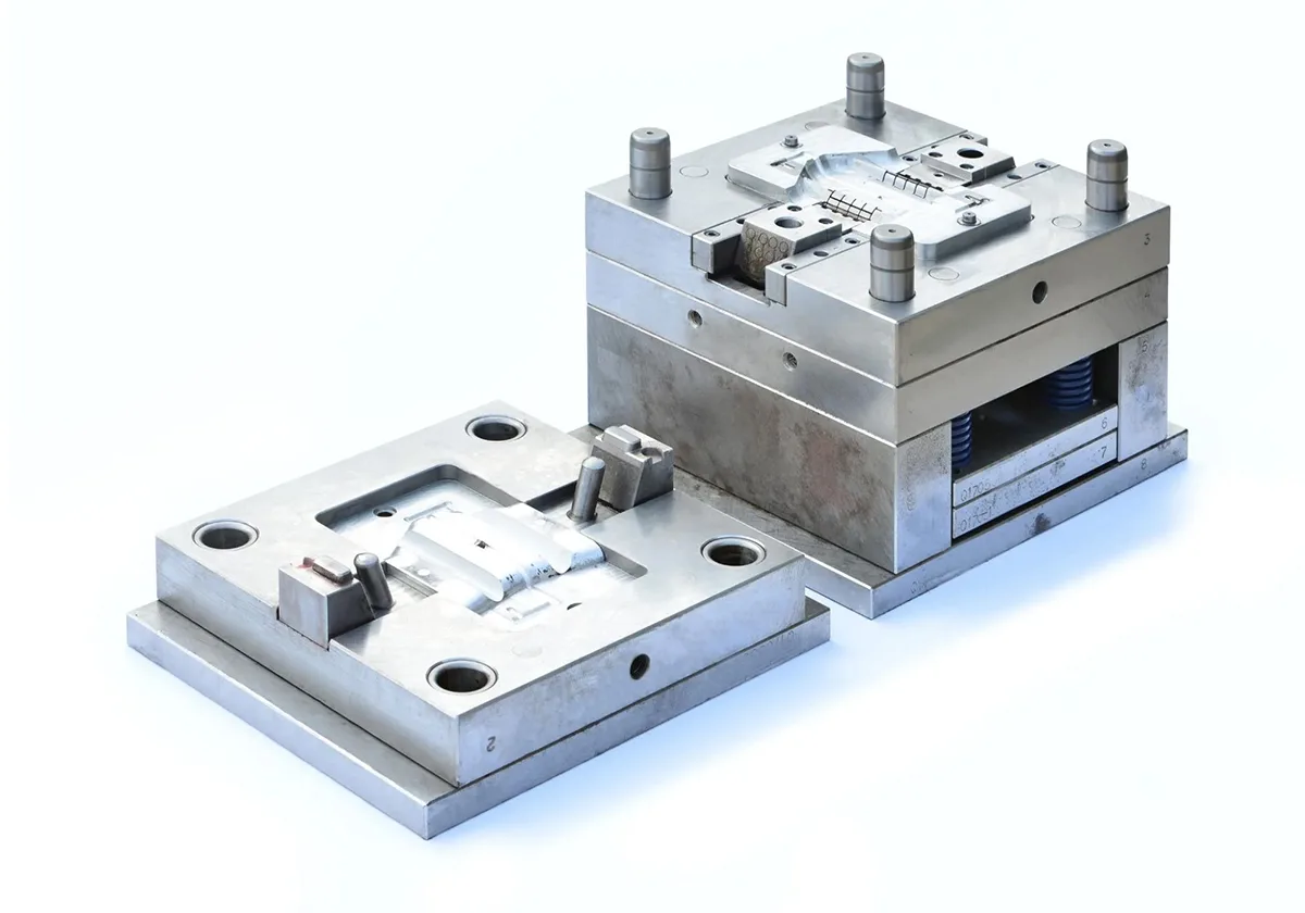
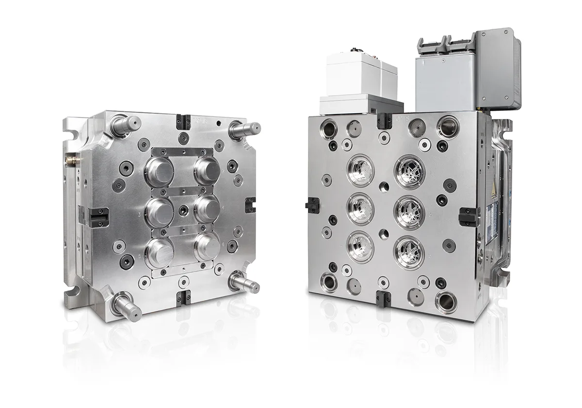
Mold design and development covers the engineering work required to turn a component design into a suitable production tool. Typically, this work includes design review, mold architecture, cavity and core design, gating, venting, cooling or thermal considerations, material selection, manufacturing, trial runs, and dimensional validation.
However, the exact workflow depends on the molding process. Plastic parts require attention to melt flow and cooling, whereas metal and ceramic injection molding also require engineers to consider binder removal, sintering behavior, shrinkage compensation, and final material properties.
Plastic Injection Mold
First, engineers review polymer flow, parting lines, gates, vents, cooling channels, ejection, and expected molding shrinkage.
Metal Injection Mold
Next, the team considers feedstock flow, green-part integrity, debinding support, sintering shrinkage, and final dimensional requirements.
Ceramic Injection Mold
Meanwhile, ceramic tooling development accounts for feedstock behavior, intricate geometry, green-part handling, debinding, and sintering-related dimensional changes.
Our Mold Development Services
Three Mold Solutions for Different Manufacturing Requirements
Because plastic, metal, and ceramic materials behave differently during forming and subsequent processing, each mold project needs its own engineering strategy. Accordingly, AOFE MIMCustom organizes mold development around the selected material system, component geometry, production goals, and final acceptance criteria.
Service 01
Plastic Injection Mold Design and Development
For plastic components, mold design determines how molten polymer fills the cavity, cools, and releases from the tool. Therefore, engineers need to assess the resin, wall thickness, geometry, surface appearance, dimensional targets, and expected production volume before finalizing the mold concept.
In addition, suitable gate locations, runner design, venting, cooling channels, and ejection mechanisms help manage filling behavior, cycle consistency, warpage, and cosmetic defects.
Typical Engineering Focus
- Parting lines, cores, cavities, sliders, and lifters.
- Gate and runner layout, venting, and polymer flow.
- Cooling efficiency, ejection, and cycle requirements.
- Resin shrinkage, dimensional control, and surface finish.
- Tool maintenance, expected production life, and part consistency.
Consequently, a well-planned plastic injection mold should reflect both the part’s functional requirements and the production process that will run it.
Service 02
Metal Injection Mold Design and Development
For metal injection molding, the tool shapes a feedstock made from metal powder and binder rather than ordinary molten metal. After molding, the component undergoes debinding and sintering; therefore, tooling engineers must consider not only the molded geometry but also the dimensional changes that occur during later processing.
Moreover, feedstock rheology, gate design, wall transitions, green-part strength, and the expected sintering response influence the final mold strategy. A successful design therefore links the cavity geometry to the complete manufacturing route.
Typical Engineering Focus
- Feedstock flow, gate position, and filling balance.
- Cavity design and green-part handling requirements.
- Shrinkage compensation based on the selected material and process.
- Part distortion risks during debinding and sintering.
- Final machining allowances and critical dimensions.
Ultimately, the tooling strategy should account for the sintered component’s functional dimensions rather than relying on the molded shape alone.
Service 03
Ceramic Injection Mold Design and Development
For advanced ceramic components, injection molding can help form intricate geometries that may otherwise require extensive machining from a dense ceramic blank. However, ceramic feedstock formulation, powder characteristics, binder behavior, and the part’s geometry all influence the design and production route.
Furthermore, the molded green component must retain enough integrity for handling and binder removal, while the later sintering stage introduces shrinkage and potential distortion. Consequently, tooling design needs to work together with material formulation, debinding, sintering, and final dimensional requirements.
Typical Engineering Focus
- Ceramic feedstock flow and mold filling.
- Complex cavities, thin features, and wall transitions.
- Green-part support and safe handling.
- Debinding conditions and sintering shrinkage.
- Final geometry, surface quality, and dimensional inspection.
Accordingly, ceramic injection mold development should connect tooling decisions with the full ceramic manufacturing process, rather than treating the mold as an isolated component.
Engineering Workflow
Mold Design and Development Process
A structured workflow helps the project team identify design risks before tooling manufacture and production qualification. First, engineers clarify the part requirements; next, they develop the mold concept, review manufacturability, and validate the tool through suitable trials and inspections.
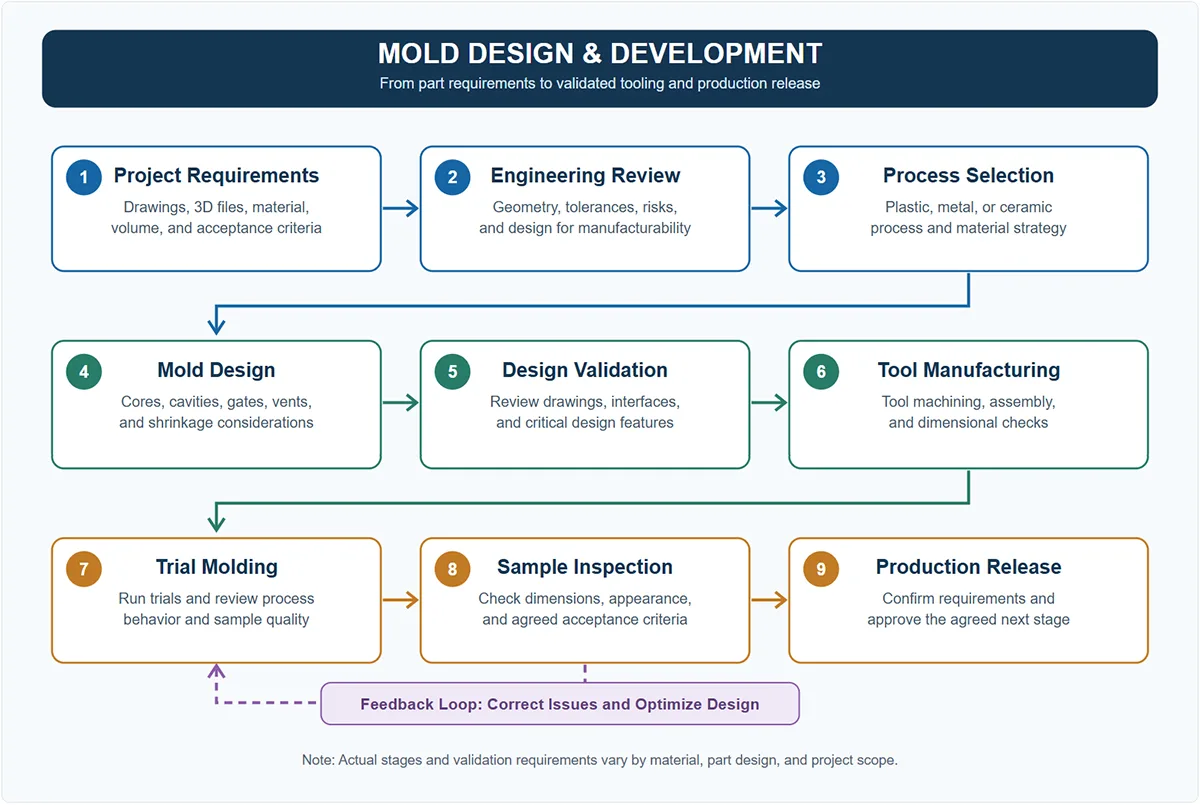
Although the workflow follows a logical sequence, engineering projects may require feedback between design, tooling, trials, and inspection. Therefore, teams should resolve significant issues before confirming the final production release.
Engineering Design Review
What Should Engineers Review Before Mold Manufacturing?
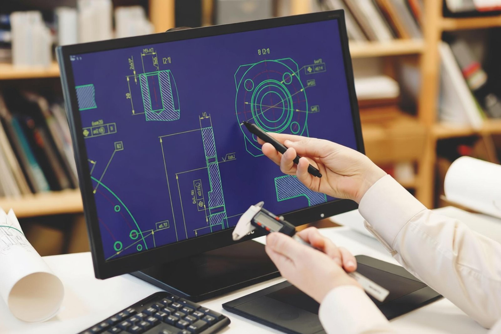
Before tooling begins, the design review should connect the component drawing with the selected molding process and the final performance requirements. In particular, the review should identify features that affect filling, part release, dimensional stability, finishing, and repeatability.
Part Geometry
First, evaluate wall thickness, ribs, bosses, holes, undercuts, parting lines, and the features that may complicate tool manufacture or part ejection.
Material Behavior
Next, examine polymer flow or powder-binder feedstock behavior, depending on whether the project uses plastic, metal, or ceramic injection molding.
Dimensional Strategy
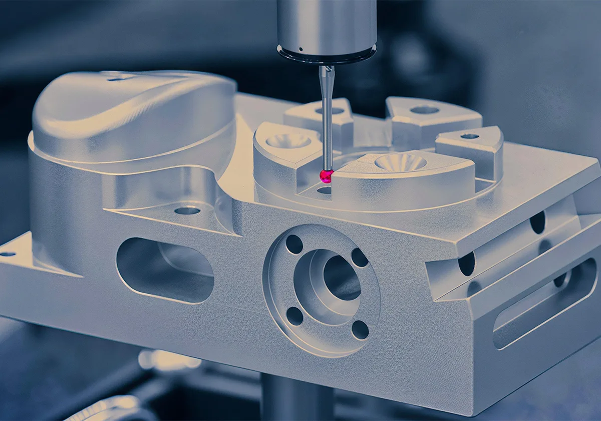
Meanwhile, identify critical dimensions, datum features, shrinkage compensation, possible distortion, and the need for secondary machining.
Tool Life and Maintenance
Additionally, consider expected production volume, wear points, replaceable inserts, maintenance access, and the required tool service life.
Quality Requirements
Finally, define the inspection method, surface appearance, tolerance requirements, sample approval criteria, and applicable documentation.
Engineering note: Mold geometry alone cannot guarantee final part quality. Instead, material characteristics, machine settings, tool condition, process stability, and downstream operations all influence the finished component.
Project Deliverables
What Can a Mold Development Project Include?
The required deliverables depend on the agreement, project complexity, and customer’s engineering standards. Accordingly, define the expected documents and validation activities before development begins so that both sides understand the project scope.
| Development Stage | Potential Deliverables | Purpose |
|---|---|---|
| Design Review | Drawing review, requirements summary, and design-risk notes. | Clarify the scope and identify major engineering concerns. |
| Mold Design | Agreed mold drawings, cavity layout, and relevant design files. | Communicate the tooling design and critical interfaces. |
| Tool Manufacturing | Tooling build, assembly, and applicable checks. | Prepare the tool for the agreed trial stage. |
| Trial and Validation | Trial samples, dimensional results, and agreed issue records. | Evaluate the part against defined acceptance criteria. |
| Project Handover | Agreed tooling documentation, maintenance guidance, and approval records. | Support the next production stage and ongoing tool management. |
Please note that not every project automatically includes every item in this table. Therefore, confirm drawing ownership, editable CAD formats, trial quantities, inspection reports, and tool storage or transfer arrangements in the quotation or project agreement.
Cross-Process Comparison
How Plastic, Metal, and Ceramic Injection Mold Design Differ
Although the three processes share the concept of shaping material inside a mold, the tooling requirements are not interchangeable. Consequently, the design team should establish the process-specific constraints before selecting the mold architecture and validation plan.
| Design Topic | Plastic Injection Mold | Metal Injection Mold | Ceramic Injection Mold |
|---|---|---|---|
| Feedstock | Thermoplastic or other suitable polymer feedstock. | Metal powder combined with a binder system. | Ceramic powder combined with a binder system. |
| Main Flow Considerations | Polymer flow, cooling, weld lines, and air traps. | Feedstock flow, green-part integrity, and filling balance. | Ceramic feedstock flow, powder loading, and green-part integrity. |
| Downstream Process | Cooling, ejection, and possible finishing. | Debinding and sintering, with optional secondary operations. | Debinding and sintering, with optional ceramic finishing. |
| Dimensional Focus | Molding shrinkage, cooling, and warpage. | Sintering shrinkage, distortion, and final metal dimensions. | Sintering shrinkage, fragile green parts, and final ceramic dimensions. |
| Validation Focus | Filling, cycle stability, appearance, and dimensional inspection. | Sintered dimensions, material properties, and functional requirements. | Sintered geometry, structural integrity, and specified ceramic properties. |
As a result, a mold concept developed for plastic parts should not automatically transfer to metal or ceramic injection molding. Instead, the engineering team must reassess material behavior, downstream processing, shrinkage, and final acceptance requirements for every project.
Applications and Custom Projects
Mold Development for Different Industries
Across industrial markets, custom molds can support components with intricate features, repeatable geometry, and application-specific material requirements. Nevertheless, the suitable process depends on the part’s function, operating environment, quantity, and performance targets.
Consumer Electronics
For compact devices, mold development may support housings, connectors, brackets, precision mechanisms, and small structural parts.
Automotive and Mobility
Similarly, automotive programs may require tooling for connectors, locking features, compact mechanisms, and other components that need repeat production.
Medical and Dental Equipment
For medical-related applications, material selection, cleanliness, traceability, and applicable regulatory requirements need careful review.
Robotics and Automation
Meanwhile, robotics projects may involve compact brackets, precision mechanisms, gears, gripper features, and other functional parts.
Industrial Equipment
In industrial equipment, custom tooling may support handles, wear-related components, control parts, and precision mechanical features.
Advanced Ceramic Components
For suitable ceramic projects, injection mold development may help form intricate electrical, mechanical, wear-resistant, or thermal-management components.
Frequently Asked Questions
Mold Design and Development FAQs
1. What information should I provide for a mold design quotation?
To start the review, provide a 2D drawing, a 3D CAD model if available, the intended material, estimated production volume, critical tolerances, and surface requirements. Additionally, explain the component’s function and identify any special inspection or documentation needs.
2. Can one supplier support plastic, metal, and ceramic injection mold projects?
Potentially, a supplier can coordinate projects across these process categories when the required engineering and manufacturing capabilities are available. However, each material system requires its own technical assessment, so confirm the scope and capabilities for your specific project.
3. Why do metal and ceramic injection molds require shrinkage compensation?
During sintering, metal or ceramic feedstock densifies and the component changes dimensions. Therefore, the mold design needs a suitable compensation strategy based on the material, geometry, process conditions, and validation results.
4. How long does mold development take?
The timeline depends on part complexity, tooling architecture, material availability, manufacturing capacity, and the number of trial or revision cycles. Consequently, a reliable schedule requires a review of the drawing, project scope, and validation requirements.
5. Can you develop a mold from an existing part sample?
An existing sample can help explain the component’s shape and intended function. Nevertheless, engineers may still need a drawing, CAD reconstruction, material identification, tolerance requirements, and approval of the proposed design before proceeding.
6. Does mold development include trial molding and sample inspection?
Trial molding and sample inspection can form part of the agreed development scope. Before starting, confirm the number of trial rounds, sample quantities, dimensional reports, acceptance criteria, and responsibility for any design revisions.
7. How can AOFE MIMCustom assess my mold project?
Start by sharing your component drawing, intended molding process, target material, expected volume, and critical dimensions. After reviewing these details, AOFE MIMCustom can discuss the engineering questions and project information needed to determine the next steps.
Start Your Mold Development Project
Looking for a Custom Injection Mold Solution?
Whether you need a plastic injection mold, metal injection mold, or ceramic injection mold, share your drawings and production requirements with AOFE MIMCustom. With the right technical information, the team can begin reviewing part geometry, material considerations, tooling scope, and validation needs.
For a faster initial review, include the latest drawing revision, material specification, target quantity, and critical-to-function dimensions.