1. What is Custom Ceramic Component Design?
Custom ceramic component design is the specialized engineering discipline of creating bespoke geometries out of advanced inorganic, non-metallic materials-such as Silicon Nitride (Si₃N₄), Alumina (Al₂O₃), Zirconia (ZrO₂), and Silicon Carbide (SiC)-to meet specific operational requirements that standard off-the-shelf parts cannot fulfill.
Unlike metal machining, where a solid block is carved away, ceramic manufacturing relies on powder metallurgy. Raw powders are mixed with binders, formed into a “green body,” and subjected to extreme heat (sintering) to achieve full density. Therefore, custom ceramic design is not just about the final shape; it is about designing a part that can survive the manufacturing process itself. It requires a deep synthesis of mechanical engineering, materials science, and thermodynamics to ensure the component does not warp, crack, or fail during the massive volumetric shrinkage that occurs inside a 1700°C furnace.
2. Key Considerations in Custom Ceramic Component Design
To ensure structural integrity and functional success, engineers must rigorously address these Design for Manufacturability (DFM) principles:
A. Avoiding Stress Concentrations (The Golden Rule)
Ceramics are highly sensitive to tensile stresses due to their lack of ductility. Sharp internal corners are strictly prohibited. All internal angles, shoulders, and intersections must incorporate generous fillets (radii). A sharp 90-degree internal corner will almost certainly act as a crack initiation site during sintering shrinkage or under operational loads. External sharp edges should also be chamfered to prevent chipping during post-sintering handling.
B. Managing Sintering Shrinkage and Tolerances
During sintering, the porous green body densifies, resulting in uniform volumetric shrinkage of typically 15% to 20%. Engineers must calculate precise oversizing factors for the green mold. “As-fired” tolerances are generally limited to ±1-2%. If the application demands tight tolerances (e.g., ±0.005 mm), the design must include excess material on critical surfaces for post-sintering CNC diamond grinding and lapping.
C. Uniform Wall Thickness
Sudden, drastic changes in cross-sectional thickness cause uneven heat transfer and differential shrink rates, creating severe internal residual stresses that can warp or fracture the part. Designs should strive for uniform wall thickness. If variations are unavoidable, they must transition gradually using long, smooth tapers rather than abrupt steps.
D. Designing for Diamond Machining
Fully sintered Si₃N₄ is nearly as hard as diamond. Traditional cutting tools cannot machine it. The design must accommodate diamond grinding wheel limitations: avoid deep narrow slots, undercuts, and complex internal cavities. Deep small-diameter holes should be formed in the green state or created via ultrasonic machining, as post-sintering drilling is expensive and prone to breakage.
E. Ceramic-to-Metal Assembly
When joining ceramic to metal, the massive Coefficient of Thermal Expansion (CTE) mismatch must be addressed. Metals expand significantly more than ceramics when heated. If rigidly constrained, the ceramic will crack. Designs must incorporate compliant interlayers, active metal brazing (AMB), or high-temperature adhesives to absorb thermal expansion differentials.
3. Industries with Highest Design Requirements
Semiconductor & Lithography (The Pinnacle)
This industry has the most extreme requirements. Wafer handlers, electrostatic chucks, and plasma focus rings demand ultra-high purity, zero particle outgassing in UHV, exceptional plasma erosion resistance, and extreme thermal stability to maintain nanometer-level alignment during rapid thermal cycling.
Aerospace & Defense
Turbine shrouds, radomes, and gyroscope bearings must survive extreme thermal shock and maintain dimensional stability above 1000°C. Design must optimize strength-to-weight ratio, leveraging Si₃N₄’s low density to reduce aircraft mass while withstanding immense centrifugal forces.
Electric Vehicles (EV)
EV traction motors at 20,000+ RPM generate stray currents. Custom Si₃N₄ hybrid bearing races and insulating rings must provide complete electrical isolation (preventing fluting) while minimizing friction. Design must account for high-speed dynamic loads and rapid thermal expansion of aluminum housings.
Medical Devices
MRI-safe instruments, implants, and micro-pump valves require strict biocompatibility and radiolucency. Design must feature mirror-polished finishes (Ra < 0.02 μm) to prevent bacterial adhesion and withstand repeated autoclave sterilization without degradation.
4. AOFE’s Design Process & Requirements
At AOFE, we engineer ceramics, not just manufacture them. Our exclusive focus on Silicon Nitride (Si₃N₄) enables a rigorous multi-stage design process:
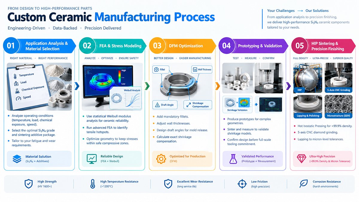
The AOFE 5-Step Process:
- Application Analysis & Material Selection: We analyze temperature, load, chemical exposure, and speed to select the optimal Si₃N₄ grade and sintering additive package tailored to your fatigue and wear requirements.
- FEA & Stress Modeling: Ceramics require statistical Weibull modulus analysis. We run advanced FEA to identify tensile hotspots and optimize geometry to keep stresses within safe compressive zones.
- DFM Optimization: We modify CAD models: adding mandatory fillets, adjusting wall thicknesses, designing draft angles for mold release, and calculating exact shrinkage compensation.
- Prototyping & Validation: For complex geometries, we produce prototypes, sinter them, and measure to validate shrinkage models before full-scale tooling commitment.
- HIP Sintering & Precision Finishing: Parts undergo Hot Isostatic Pressing for >99.9% density, followed by 5-axis CNC diamond grinding and lapping to micron-level tolerances.
5. The AOFE Advantage
Unmatched Si₃N₄ Specialization
Our entire infrastructure is dedicated exclusively to Silicon Nitride. Our metallurgists understand microstructural grain boundary engineering to maximize fracture toughness and rolling contact fatigue life.
In-House HIP Sintering
We operate advanced HIP furnaces at 200 MPa / 1750°C, guaranteeing elimination of all internal micro-porosity-critical for high-stress components that cannot afford sub-surface crack initiation.
Advanced Metrology & NDT
Every component undergoes ultrasonic C-scanning and X-ray radiography for internal integrity verification. CMM and white-light interferometry certify micron-level tolerances and nano-level finishes.
Aerospace-Grade Traceability
Full lot traceability with comprehensive data packages: raw powder chemistry certificates, sintering logs, dimensional reports, and NDT results for aerospace and medical compliance.
6. Custom Ceramic Design FAQ
Q1: What is the most critical rule in custom ceramic component design?
Avoiding sharp internal corners and sudden cross-sectional changes. All internal corners must incorporate generous fillets to prevent crack initiation during sintering and under operational loads.
Q2: How do engineers account for shrinkage?
Engineers design the green body oversized using precise shrinkage factors (15-20%), leaving extra material on critical dimensions for post-sintering CNC diamond machining to achieve final tight tolerances.
Q3: Which industry has the most demanding requirements?
Semiconductor and lithography, demanding ultra-high purity, zero outgassing in UHV, plasma erosion resistance, and extreme thermal stability for nanometer-level alignment.
Q4: Why is Si3N4 preferred for dynamic components?
Superior thermal shock resistance, highest fracture toughness, excellent rolling contact fatigue life, and low CTE make it ideal for high-speed bearings, EV motors, and aerospace turbines.
Q5: What is AOFE’s design process?
5-step process: Application Analysis, FEA Stress Modeling, DFM CAD Optimization, Prototyping & Validation, and HIP Sintering with Precision Diamond Machining, backed by NDT.
Q6: Can ceramics be joined to metal?
Yes, using compliant interlayers, active metal brazing (AMB), or high-temperature adhesives to manage CTE mismatch and prevent ceramic cracking from thermal stresses.